MV Agusta BRUTALE 910 S Workshop Manual Download Page 102

- 86 -

Engine

B

1

2

2

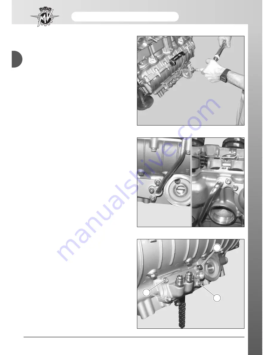
Then, remove the oil head delivery conduit by remo-
ving the lower and upper fixing screws respectively.

Unscrew the three screws (

2

) and remove them; then

remove the special screw (

1

) placed on top left.

LUBRICATION COMPONENTS:
OIL TUBING SUPPORT PLATE

Disassembling and reassembling

To remove the oil tubing support plate, the oil filter sup-
port should be removed first, as described in the “Oil
sump” paragraph.

Summary of Contents for BRUTALE 910 S

Page 1: ...Workshop engine manual MVAGUSTA BRUTALE 910 S MVAGUSTA BRUTALE 910 S...

Page 2: ...2005 The reproduction even partial of this document is forbidden without prior written agreement of MV Agusta S p A Part N 8A00A6440 Edition N 1 Printed December 2005...

Page 3: ...Workshop engine manual MVAGUSTA BRUTALE F4 910 S...

Page 4: ...e g the collection of spare parts the preparation of tools and equipment etc To reach the part to be repaired limiting the work to the essential operations With regards to this a valid help would be t...

Page 5: ...Freni 3 A B General Index GENERAL DESCRIPTION ENGINE...

Page 6: ......

Page 7: ...1 General description A SECTION A Revision 0...

Page 8: ...MMARY HOW TO CONSULT THIS MANUAL PAGE 3 THE PURPOSE OF THIS MANUAL PAGE 3 GLOSSARY AND SYMBOLS PAGE 4 RIGHT HAND AND LEFT HAND STANDARD PAGE 6 SAFETY PAGE 7 WARNING PAGE 9 INDEX PAGE 9 OPERATIVE TECHN...

Page 9: ...cial tools and other information See the symbols lists for their significance The procedures are described step after step PURPOSE OF THE MANUAL Principally this manual has been written for MV Agusta...

Page 10: ...of the relative cylinder In order to allow the motor to function under the best conditions it is necessary that all of the couplings are within the accepted toler ances established A tight coupling is...

Page 11: ...ecommended brake fluid Use the recommended suspension fluid Use the recommended coolant Use the recommended thread locking fluid Use the recommended sealant Use the recommended adhesive Carry out accu...

Page 12: ...ylinder 3 Cylinder 4 Cylinder 1 Cylinder 2 RIGHT HAND AND LEFT HAND STANDARD To clarify the right hand and left hand standard that is used in this manual herewith below is a diagram of the motorcycle...

Page 13: ...nment Keep used oil out of the reach of children Engine coolant Under certain situations the ethylene glycol contained in the engine coolant is inflammable and its flame is invisible Ethylene glycol w...

Page 14: ...ly nitrogen to pressurise the shock absorber The use of unstable gases can cause explosions that could cause burns Do not place the shock absorber near to flames or sources of heat as this could cause...

Page 15: ...be conducted without damaging the motorcycle Thoroughly clean the motorcycle before disassembling it During disassembly clean all parts and place them in con tainers respecting exactly the order of di...

Page 16: ...ATION The registration number of the motorcycle is stamped on the right side of the steering head The engine registration number is stamped on the upper engine casing near the forks Below is an exampl...

Page 17: ...B 1 Engine SECTION B Revision 0...

Page 18: ...4 CYLINDER AND PISTON GROUP PAG 44 CLUTCH PAG 50 GEAR AND GEAR CONTROL PAG 57 ELECTRICAL COMPONENTS PAG 64 OIL PUMP PAG 66 WATER PUMP PAG 68 STARTING PAG 72 MOTOR SHAFT PAG 74 BEDPLATE PAG 76 CAPS PAG...

Page 19: ...ws 25 medium M6 gear control screws 8 medium BEDPLATE ACCESSORIES Alternator tightening screws 25 Motor starter tightening screws 10 Water pump tightening screws 8 Neutral switch screws 10 FREE WHEEL...

Page 20: ...rews 8 M6 bearing clamp screw 12 medium Extractable gear change cap M8 screws 25 M6 torque screws 10 M8 torque screws 25 Plate screws for oil radiator connectors 10 Support screws for oil filter 40 In...

Page 21: ...ion Procedure Motor oil Substitution At least every year Motor oil filter Each time engine oil is renewed Cooling liquid Check Top up Substitution Every two years Cooling system Check for leaks Electr...

Page 22: ...eck operation Side stand Check operation switch Rear wheel hub Check Substitution Big fork bearings Check lubrification Big fork chain shoes Check substitution Frame plate chain shoes Check substituti...

Page 23: ...and fluids MV Agusta recommends purchasing the product from its authorized dealers The engine oil AGIP Racing 4T 10W 60 has been specially designed for the F4 engine Should this lubricant be unavailab...

Page 24: ...l diameter Valve stem Exhaust Inlet Valve spring Internal External Valve cam clearance Exhaust Inlet STANDARD 24 6 mm 28 6 mm 1 mm 0 02 0 04 mm 0 01 0 03 mm 4 5 mm 4 475 0 005 mm 4 485 0 005 mm 33 8 m...

Page 25: ...1st 2nd Oil scraper Maximum segment cylinder play 1st 2nd Scraper CLUTCH Disk thickness Springs STANDARD 0 038 0 067 mm 0 004 0 012 mm 0 015 0 032 mm 0 8 mm 0 8 mm 1 5 mm 0 2 0 4 mm 0 2 0 4 mm 0 2 0...

Page 26: ...ction gear limit Primary 5a 6a Secondary 1a 2a 3a 4a Fork pit play BEDPLATE DRIVE SHAFT Bed bearing functioning play Connecting rod bearing Functioning play Drive shaft axial play STANDARD 0 35 0 15 m...

Page 27: ...ng rings in deformable material and self blocking nuts must always be substituted The bearings are dimensioned for a determined num ber of working hours Substitution is therefore recom mended in consi...

Page 28: ...of the reported range check the following points A carbon deposits on the walls of the combustion chamber and on the piston ceiling B lthe head gasket is not of the correct measure ments N B If the co...

Page 29: ...for mance of the engine When carrying out operations on throttle bodies it is advisable to remove certain parts of the bodywork such as Passenger seat Rider seat Tank side panels Ignition switch cover...

Page 30: ...ht side of the motorcycle near the expansion tank of the coolant Start the MDST diagnosis software and go to the Display instrument panel screen Set the ignition switch to ON Select the Connect option...

Page 31: ...rottle opening using only the appropriate screw on the throttle opening pulley It is recommended not modify the throttle potentiome ter position because the throttle has been set during the production...

Page 32: ...probes registering CO inside the specific tool kit code 8000A4686 Assemble the 2 pipes with their Y union also supplied with tool kit code 8000A4686 on the probes registe ring CO Connect the Y union w...

Page 33: ...m the closed position Start the engine and warm it up During this phase you should not accelerate because the high depression created in the induction lines could pipe the mercury from vacuometer The...

Page 34: ...m the closed position The number of turns per minute must fall within the fol lowing values 1150 1250 turns min Check the CO value using the exhaust gas analyser This value must be between the followi...

Page 35: ...rm in the order as follows assemble the rubber plug on the gearcase lower side apply a new seal plate assemble the gearcase on the air filter compartment restoring the earth bonding disassemble the ex...

Page 36: ...pply neither oil nor other types of substances GR Apply grease SS Apply silicone sealing HSC Apply HSC Molikote M Apply mastic for gaskets CYLINDER HEAD A B C D E F G H I L N m 12 8 45 8 36 Tightening...

Page 37: ...cover 2 proceed carefully so as not to damage the gasket 3 When refitting it is essential to apply silico ne sealant as shown in the figure at the beginning of the chapter On the left side of the moto...

Page 38: ...te the drive shaft up to the point where the n 1 piston is at MSP in burst phase In this position the T notch on the phonic wheel is lined up with the reference notch on the bedplate The cams relative...

Page 39: ...the chain tensioner by means of the two tightening screws First remove the 2 external stands 4 and 5 of the camshafts by means of the four screws each internally hexagonal At the same time remove the...

Page 40: ...l NO OIL Do not apply neither oil nor other types of substances GR Apply grease SS Apply silicone sealing HSC Apply HSC Molikote M Apply mastic for gaskets A B C D E F G H I L N m 21 8 8 12 Tightening...

Page 41: ...ghtening screws In case it should be necessary to substitute the distrib ution chain at the expected mileage see the pro grammed maintenance chart it is advisable also to substitute the gears on the c...

Page 42: ...he head begin ning from the external ones proceeding towards the internal ones following the sequence indicated in the figure On each encarcement there is a washer Be carefully no to let it fall into...

Page 43: ...on of the head group Remove carbon deposits from the combustion cham bers Clean away eventual encrustments from the canalizations of the cooling liquid Check to be sure that are no crack and that the...

Page 44: ...inder plane distance with the n 8000A3406 tool tightening the head nuts at 12 N m The choice is made following table below The cylinder base gaskets always have the same thickness see table Distance b...

Page 45: ...g grease of the HSC MOLIKOTE type only on the nut threads Do not apply grease on the encarcement threads which must be well cleaned and degreased Screw the bolts with a brugle key and press them at 35...

Page 46: ...t phase in this position T notch on the phonic wheel is in line with the reference notch on the bedplate Remove the copper thread from distribution chain keep the chain tightened If the middle gears o...

Page 47: ...OT in the MSP position Fit the distribution chain on the intermediate gear Position the intermediate gear being careful that the pellet on the gear corresponds with the pellet on the bedplate being ca...

Page 48: ...32 Engine B Pin number 24 Pin number 25 Pin number 1...

Page 49: ...assembly the chain tensioner and check the correct working of each part The internal pin must run clearly and the inner spring must give a quick response Replace the assembly in case of malfunction If...

Page 50: ...8 Nm Place the adduction oil tube at the head greasing the O Rings Dismounting cylinder head pieces In order to carry out this procedure the following tools are necessary tool n 800094796 to disassemb...

Page 51: ...use tool n 95179 so as to avoid bending the valves C Assemble the head on tool n 800094796 D Hammer on the superior disk with a rubber hammer to unblock the semi cones E Press the springs on the super...

Page 52: ...36 Engine B 800094798...

Page 53: ...thin or irregular it will be necessary to repair it Thickness of the stroke surface of the slot standard exhaust inlet 1 mm E The repair must be carried out by milling the slots using the appropriate...

Page 54: ...idering that the assem bling interference should be 0 10 0 15 mm C Valve slots are furnished with an increased replace ment part of 0 03 mm on the external diameter D Slowly and evenly heat the head a...

Page 55: ...between guide and valve stem it is necessary to measure the play using a control tampon and micrometer The control tampon 800095429 4 55 must not pass In the case of substituting the guide valve it i...

Page 56: ...be sure the valve slides freely in the valve guide otherwise coat it with a 4 5 H7 reamer or broach N 8000A2625 Valve The stem diameters must not fall below 4 485 3 100 mm inlet 4 475 3 100 mm exhaust...

Page 57: ...ck to be sure that the free value of length is not inferior to the suggested limit and in such case substi tute the springs Internal spring L 33 8 mm Service limit 33 3 mm External spring L 37 9 mm Se...

Page 58: ...inserted D Using a rubber hammer strike a slight blow on the valve so as to place the semi cones Before placing the semi cones be sure that the head is not resting on a plane in order to avoid distort...

Page 59: ...tion opening A Rotate the drive shaft until completely unwinding the springs relative to the valves on which intervening MSP in burst phase B Measure valve play with a thickometer C Calculate the D di...

Page 60: ...IL Apply motor oil NO OIL Do not apply neither oil nor other types of substances GR Apply grease SS Apply silicone sealing HSC Apply HSC Molikote M Apply mastic for gaskets A B C D E F G H I L N m 8 T...

Page 61: ...age the elastic strips Work on one piston at a time to continue the removal First remove the 2 pistons which are at the MSP and rotate the drive shaft at 180 and disassemble the 2 remaining pistons Re...

Page 62: ...lso substitute the pistons and elastic strips The cylinder is marked with a letter which indicates the class it belongs to A and B cylinders and A and B pistons exist which must be coupled with the sa...

Page 63: ...the shell base in a perpendicular position to the piston pin axle These measurements must be carried out at a stabi lized temperature of 20 The play between piston and cylinder must fall between 0 03...

Page 64: ...iceable it is recom mended to change the pistons as well Segment cylinder coupling Introduce the 5 mm segment under the head plane being careful to position it well in square and to mea sure the dista...

Page 65: ...from falling into the oil cup Always use new blocking rings Assemble a new gasket between the cylinder and bed plate Position the clamps onto the pistons in the direction shown in the sketch Oil cyli...

Page 66: ...pply grease SS Apply silicone sealing HSC Apply HSC Molikote M Apply mastic for gaskets A B C D E F G H I L N m 8 140 10 Tightening torque Thread blockers Average 1 code 8000A2561 q ty 7 2 code 8000A2...

Page 67: ...which makes the disk pusher plate function Clutch disassembly In order to carry out this function the following special tool is necessary Utensil n 800079015 Remove the 11 screws which fasten the clut...

Page 68: ...in order to prevent the oil seal 1 from damaging See the illustration on the following page with the slot for the lubrica tion facing towards the friction side Manually remove all of the attrition di...

Page 69: ...Engine 53 B Remove the spacer 8 and shaving washer 9 Disassemble the clutch block following the sequence in the figure 8 9...

Page 70: ...wed wear limit 2 8 mm No signs of burning grooves or other damages are allowed Replace the whole plates group even if only one is damaged Put the plate on a table and check the deformation The maximum...

Page 71: ...refore has a sharp corner and a rounded corner Position the rounded cor ner on the engine side Assemble the disk holding hub by first mounting the 5 piece see FRICTION fig then the 4 spring with the s...

Page 72: ...at 140 N m using a medium thread locking product and then bend the safety washer Assemble the disk pusher plate tightening the screws with springs as 10 N m Substitute the cap gasket Aline the centeri...

Page 73: ...NO OIL Do not apply neither oil nor other types of substances GR Apply grease SS Apply silicone sealing HSC Apply HSC Molikote M Apply mastic for gaskets A B C D E F G H I L N m 140 8 8 6 25 M8 25 Ti...

Page 74: ...mer delicately beat on the primary shaft from the clutch end holding a hand on the gear cap until it moves from the bedplate Slide the gear group out It is important to reassemble the friction rod fro...

Page 75: ...5 mm Groove width of a new drum 7 05 7 15 mm Wear limit 7 35 mm The new fork pin diameter is equal to 6 8 6 9 mm Wear limit 6 7 mm Verify the working clearance between the fork pin and the shift drum...

Page 76: ...ne B Primary and secondary shaft Check the two shafts separate ly so as to avoid confusion of similar components Place the components in such a way as to facilitate the correct positioning dur ing rea...

Page 77: ...side of the gear box Verify the control quotas indicated on the sketch in the figure Gear selection forks Visually inspect the gear selection forks to look for folds or other damage Every fork that ap...

Page 78: ...e 2 shafts on the n 8A0094792 engine simulation tool Install a shift pedal and check the gear box is correctly working Always install a new washer under the pinion at reassem bly Carefully degrease th...

Page 79: ...ach gear ing once inserted presents a fork pit play equal to 0 2 0 3 mm placing it on both ends of the coupling The fork must be free Assemble the gasket on the internal end Before inserting the gear...

Page 80: ...oil NO OIL Do not apply neither oil nor other types of substances GR Apply grease SS Apply silicone sealing HSC Apply HSC Molikote M Apply mastic for gaskets A B C D E F G H I L N m 10 25 10 22 12 6...

Page 81: ...torsions fall Assembly Grease the torsions and O Rings Insert the pallets together with the torsions Manually bring the screws together thus tighten them at 25 Nm Starter motor Removal Remove the two...

Page 82: ...motor oil NO OIL Do not apply neither oil nor other types of substances GR Apply grease SS Apply silicone sealing HSC Apply HSC Molikote M Apply mastic for gaskets A B C D E F G H I L N m 8 Tightenin...

Page 83: ...lutch end To disassemble the oil pump remove the external screws Separate the various components as indicated in the figure Visually check the components to be sure that there are no lines of deforma...

Page 84: ...y motor oil NO OIL Do not apply neither oil nor other types of substances GR Apply grease SS Apply silicone sealing HSC Apply HSC Molikote M Apply mastic for gaskets A B C D E F G H I L N m 8 Tighteni...

Page 85: ...er pump pieces After having extracted the pump from the bedplate disassemble the pump as follows A Remove the tightening screws from the pump body 1 and separate the latter from the cap Be careful no...

Page 86: ...s and the O Ring condition Verify that the impeller does not show signs of giving away or slits Verify the absence of excessive play between the impeller shaft and bearings In case of wear of one of t...

Page 87: ...D Insert the two seeger rings 3 E Insert the two O Rings 2 Be careful not to let the two centering bush es fall 9 F Insert the two pump body tightening screws 1 and unite the latter to its cap Water...

Page 88: ...NO OIL Do not apply neither oil nor other types of substances GR Apply grease SS Apply silicone sealing HSC Apply HSC Molikote M Apply mastic for gaskets A B C D E F G H I L N m 10 55 25 Tightening to...

Page 89: ...heel only turns clockwise Assemble the group on the tool 800094795 and block the screw with a dynamometric key at 25 N m and MEDIUM THREAD BLOCKER Reassemble the male torsion joint on the generator ti...

Page 90: ...H I J K N m 25 Tightening torque Thread blockers Medium OIL Apply motor oil NO OIL Do not apply neither oil nor other types of substances GR Apply grease SS Apply silicone sealing HSC Apply HSC Moliko...

Page 91: ...ment has to be carried out on the princi pal axle of the stem after having tightened at 35 N m If substitution of one or more parts is necessary it is sufficient to follow the indications of the lette...

Page 92: ...0 22 8 14 25 30 Tightening torque Thread blockers Medium Medium Medium Medium OIL Apply motor oil NO OIL Do not apply neither oil nor other types of substances GR Apply grease SS Apply silicone sealin...

Page 93: ...O OIL Do not apply neither oil nor other types of substances GR Apply grease SS Apply silicone sealing HSC Apply HSC Molikote M Apply mastic for gaskets A B C D E F G H I L N m 10 25 10 8 35 Tightenin...

Page 94: ...lefts clean it by using compressed air at a low pressure blown from inside to outside Remove the oil filter support by unscrewing the relative screw Check that oil pressure adjusting valves A and B ar...

Page 95: ...Engine 79 B Position the gasket and move the screws close manu ally Tighten the sump screws to 10 Nm 10 N m...

Page 96: ...e size 6 screws including the one for the blow by cap Do not forget to unscrew the screw inside the carter indicated with the number 17 in the figure At the same time remember to unscrew the screws po...

Page 97: ...th a number using a marker For example the bushing removed from the n 1 bearing of the superior carter starting from the left will be identified by the mark S1 For the couplings refer to the groups th...

Page 98: ...tolerance The function play of the bench bearings must be between 0 012 0 038 mm Service limit is 0 06 mm The function play of the connecting rod bearing must be between 0 036 0 061 mm With a service...

Page 99: ...e the n 5 support as it carries out the function of the motor shaft centering Put the new cap on the right side after having put the silicone type paste on the cap s surface between cap and carter bea...

Page 100: ...Reassemble the bearing on the inferior semi carter with the locks facing each other and turned inward the bedplate Be sure that the centering bushes are installed on the inferior semi carter Spread a...

Page 101: ...e 8 screws marked with the num bers 1 to 12 and tighten them at 10 N m 60 while the remaining M8 are tightened at a torque of 25 N m Tighten the M6 screws at 10 N m Tighten all the screws inversely to...

Page 102: ...spectively Unscrew the three screws 2 and remove them then remove the special screw 1 placed on top left LUBRICATION COMPONENTS OIL TUBING SUPPORT PLATE Disassembling and reassembling To remove the oi...

Page 103: ...and position them in their seats respectively as shown in the figure Position the filter support on the base as per guiding and centering it refer to the special screw 1 for fixing the oil cooler unio...

Page 104: ...e Apply a medium thread blocker Loctite 243 and tigh ten the nipples to a clamping torque of 30 Nm Verify the three O rings placed in the back part of the oil tubing support plate for wear and substit...

Page 105: ...and position the upper part of the conduit in the seat arranged within the head and the lower part of the counduit in the seat arranged in the oil tubing support plate Tighten the upper fixing screw...

Page 106: ...nly use original components of MV Agusta Take a new rubber clamp from the motor s oil filter kit and place it on the filter as shown in the figure to the left Only use new parts Let the rubber clamp s...

Page 107: ...appropriate tool and a tor que wrench TOYO ROKI oil filter FACOM D 139 tool Part code 8000A4317 Oil filter torque wrench 24 N m After having tightened the filter take out the clamp for engine oil fil...

Page 108: ...4 further the position marked previously 1 1 5 mm Once completed the assembly ensure that the clamp lock of the engine oil filter is at a range between 1 and 1 5 mm from the screwhead on the supportin...

Page 109: ...t peg inserted in the rubber bulb support 1 on the right side 1 LUBRICATING COMPONENTS OIL RADIATOR Disassembling Remove the engine radiator support fixing screw pla ced on the left side This figure a...

Page 110: ...rt peg in the support 1 on the right side making the oil radiator move from left to right 1 Connect the engine radiator anchor rod 1 on the left side 1 Put the radiator engine support on the left side...

Page 111: ...connector with engine oil Tighten the pipes and connectors at the prescribed torque Reconnect the oil delivery and return pipings with the nipples of the oil pipings support flange lubricating previo...

Page 112: ...8A00A6440 Part No Edition No 1...

Reviews: