background image

VJ-2606 INSTALLATION MANUAL

3

VJ2606E-I-01

1

2

1

1

3

4

3

4

1

2

2

2

1

1

1

1

2

e

g

d

c

b

f

a

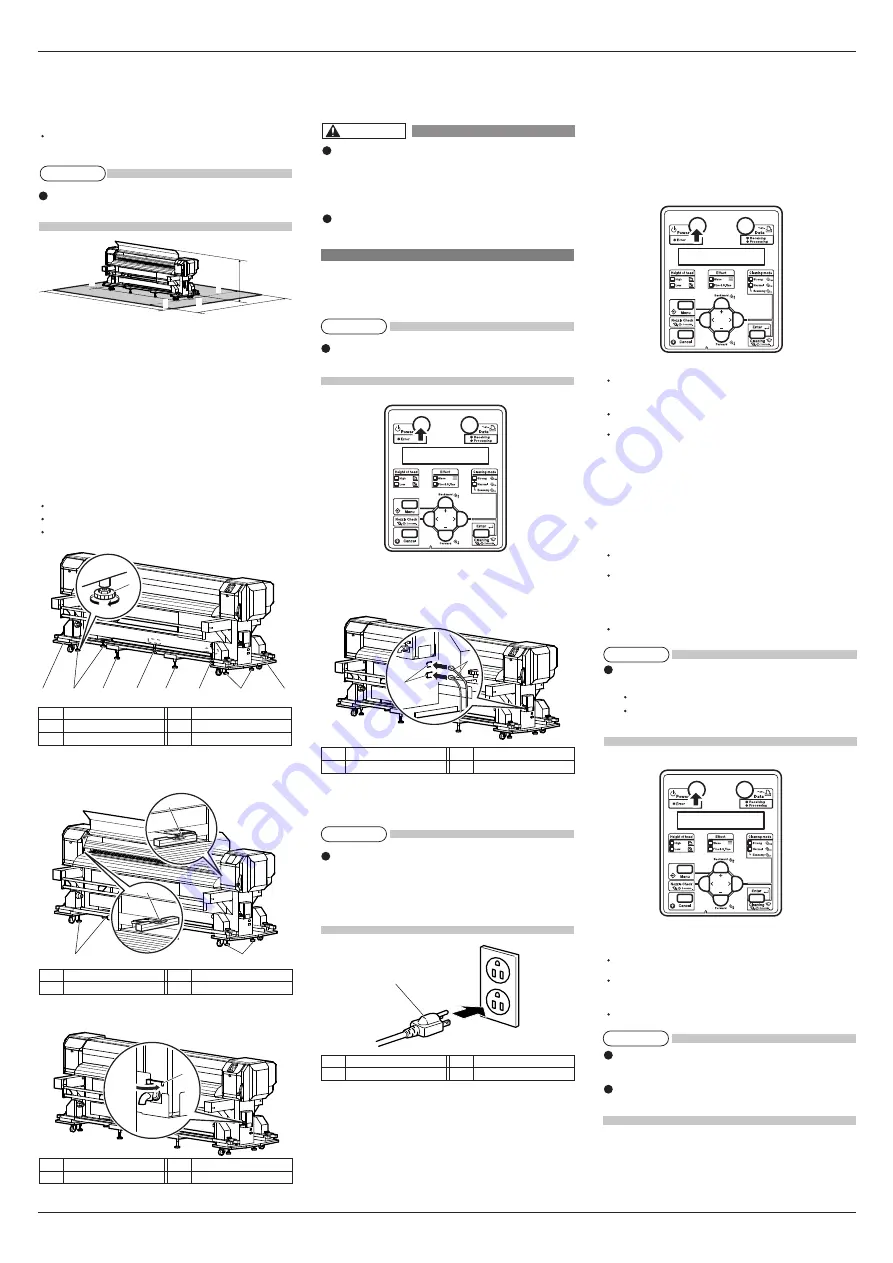
3.1.2 Installation space

Install on a level floor which meets the following con-

dition.

It has enough strength to support the weight of the 

printer and the stand.

For the weight of the printer and the stand, refer to 

the Operation Manual.

a = 650 mm

b = 1,000 mm

e = 1,250 mm

c = 1,000 mm

f = 5,200 mm

d = 1,000 mm

g = 2,950 mm

3.2 Installation procedure

Install this product to the installation place in accord-

ance with the list shown below.

1. Carry the printer to the installation place.

2. Turn the following adjusters in the direction as 

shown below to prevent the printer from moving.

Stands: adjusters (4)

Winding units: adjusters (2)

Feed units: adjusters (2)

3. Set the spirit level on the right and left platens and 

adjust so that the printer stays flat.

4. Confirm that the waste fluid valve is closed.

4 Connecting the power cable

This section explains how to connect the power cable.

Make sure that the included power ca-

ble is used.

If other power cables are used, it may 

cause an electric shock  or fire.

Do not use a damaged power cable. It 

may cause an electric shock or fire.

Follow the steps below to connect the power cable.

1. Confirm that the product is turned OFF.

If the [Power] key is pressed, the product is turned 

ON. Press the key again, and turn OFF the power.

2. Connect the power cables (x 2) to the AC inlets (x 2) 

on the right of the product.

3. Correctly insert the power cable plug into the power 

socket.

To use the two power cables plugged in the inlets, 

a total capacity of 24 A or over is required. If the 

power source cannot supply the required capacity, 

plug the two power cables in the different power 

sources respectively.

5 Turning the power ON/OFF

This section explains how to turn ON/OFF the printer.

5.1 Turning the power ON

Follow the procedure below to turn ON the printer.
1. Press the [Power] key on the operation panel to 

turn ON the printer.

The Power lamp on the operation panel lights up 

in green.
The printer starts initial operation.
When the initial operation is complete, the printer 

enters normal status.

5.2 Turning the power OFF

Follow the procedure below to turn OFF the printer.
1. Regarding the operating condition of the printer, 

confirm the following.
Printing or other operations are not in progress.
The operation panel is in normal status.

2. Press the [Power] key on the operation panel to 

turn OFF the printer.
The Power lamp on the operation panel turns OFF.

If the operation panel is in the following status, the 

power is ON.

The [Power] key is pressed in.

The Power lamp lights up in green.

Press the key once again and turn OFF the power.

3. The printer starts operating to turn the power OFF.

The operation panel displays "Power Off".
All the lamps on the operation panel and the LCD 

monitor are turned OFF.
The printer automatically turns the power OFF.

After turning OFF the printer, wait for 10 seconds 

or longer to turn it ON again.
When not using the printer for a long period, push 

the media loading lever to the back.

4. When you will not use the printer for a long period 

of time, raise the media loading lever.

  No.

Name

1

 Adjuster

3

Winding unit

  No.

Name

2

 Stand

4

Feed unit

No.

Name

1

Spirit level 

No.

Name

2

Adjuster

No.

Name

1

Waste fluid valve

No.

Name

1

AC inlet

No.

Name

2

Power cable 

No.

Name

1

Power cable

WARNING

NOTE

NOTE

NOTE

NOTE

NOTE

Summary of Contents for VJ-2606

Page 1: ...tructions in this man ual before installing this product Installation flow chart The broad steps for installation are shown below There are instructions for each section beginning on the next page 1 Confirming bundled items 1 1 Items in the printer box 1 2 Items in the accessory box 2 Assembling 3 Installation 3 1 Installation environment 3 2 Installation procedure 4 Connecting the power cable 5 T...

Page 2: ... this printer and remove the material 4 Close the front cover 5 Remove the following components attached to both sides of the cushioning roller using the Phillips screw driver included with this printer Screws 2 Cushioning roller fastening material 2 6 Remove the following components attached to both sides of the tension roller using the Phillips screwdriver included with this printer Screws 2 Ten...

Page 3: ... is required If the power source cannot supply the required capacity plug the two power cables in the different power sources respectively 5 Turning the power ON OFF This section explains how to turn ON OFF the printer 5 1 Turning the power ON Follow the procedure below to turn ON the printer 1 Press the Power key on the operation panel to turn ON the printer The Power lamp on the operation panel ...

Page 4: ...nd is displayed on the operation panel If the Nozzle check printing is performed immedi ately after the ink replenishment is complete the following results may occur Printed line becomes blurred The data is not partially printing In such cases follow the Operation Manual 6 2 3 Head cleaning and charge a small amount of ink Then check the printing result If there is no improvement in the print resu...

Page 5: ...a short distance by pressing the key on the operation panel so that the media is not slack or slanted If you release your grip on the roll media while it is being wound the media may slip off the media feed slot and fall behind the printer Make sure that the right end of the roll media does not go beyond the media loading mark It may af fect print quality When loading roll media set each side of t...

Page 6: ...el and feed the roll media to the media tube on the winding unit 4 Pull the roll media out of the media feed slot and attach the media to the media tube using tape so that they are parallel to each other When setting roll media to the winding units Make sure that there are no wrinkles or slack parts in either front or rear of the media Attach the roll media to the media tube with the printing side...

Page 7: ...ning was not enough to re move blurred or missing parts in the check pattern perform powerful cleaning If those problems above were not improved after a few times of head cleaning refer to the Operation Manual 7 Troubleshooting and perform required procedures 7 Perform nozzle check again and check the condi tion of the print head 10 Manual composition This product includes the following three manu...

Page 8: ...toh co jp MUTOH AMERICA INC Tel 1 480 968 7772 Fax 1 480 968 7990 E mail sales mutoh com http www mutoh com MUTOH EUROPE N V Tel 32 0 59 561400 Fax 32 0 59 807117 E mail mutoh mutoh be http www mutoh be MUTOH DEUTSCHLAND GmbH Tel 49 0 2159 913430 Fax 49 0 2159 913456 E mail Mutoh Sales t online de ...

Reviews: