VJ-2606 INSTALLATION MANUAL
VJ2606E-I-01
2
1
1
2
2
8
9
10
11
3
4
5
6
3
2
1
1
3
2
2
3
1
2
7
1
2
1
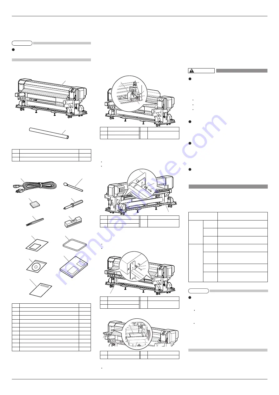
No. Name Q'ty
1
Printer main body
1 set
2
Media tube
1
No. Name Q'ty
1
Power cable
2
2
Clean stick
10
3
Flushing box sponge
10
4
Phillips screwdriver
1
5
Forceps
1
6
Spirit level
1
7
Paper towel
5
8 Tray 1
9
Operation Manual CD
1
10
Quick Reference
1
11
Installation manual (this manual)
1
More than 2940 Pa (300 kg/m
2
)
Power
Specifica-
tion
Environm-
ental
conditions
Floor strength of
installation place
Power
Supply
Frequency
Range
AC90V - 132V / 198V - 264V
50 / 60Hz ± 1Hz
Power
capacity
Change
rate
Operative
condition
Archiving
environment
Guaranteed
range of
printing
accuracy
Main: 12 A / 8 A
Heater: 12 A / 8 A
Temperature: 20 °C to 32 °C
Humidity: 40 % to 60 %, No Condensation
Temperature: 22 °C to 30 °C
Humidity: 40 % to 60 %
Temperature: within 2 °C per hour
Humidity: within 5 % per hour
Temperature: -20° C to 60 °C
Humidity: 20 % to 80 % ,
No Condensation (Ink unfilled)
No.
Name
1
Head unit
2
Screw
No.
Name
3
Head unit fastening
material (metal plate)
No.
Name
1
Cushioning roller
2
Screw
No.
Name
3
Cushioning roller
fastening material
No.
Name
1
Tension roller
2
Screw
No.
Name
3
Tension roller
fastening material
No.
Name
1
Maintenance cover (Left)
No.
Name
2
Tray
1 Confirming bundled items
After unpacking, please confirm that the product has
not damaged and no components are missing.
If any items are damaged or missing, contact
MUTOH local dealer.
1.1 Items in the printer box
1.2 Items in the accessory box
2 Assembling
This product has fastening materials in the place
shown below.
Detach all protective materials in accordance with the
following steps.
1. Remove all tapes from each cover.
2. Open the front cover.
3. Remove a screw from the head unit fastening material
(metal plate) using the Phillips screwdriver included
with this printer, and remove the material.
4. Close the front cover.
5. Remove the following components attached to both
sides of the cushioning roller using the Phillips screw-
driver included with this printer.
Screws (2)
Cushioning roller fastening material (2)
6. Remove the following components attached to
both sides of the tension roller using the Phillips
screwdriver included with this printer.
Screws (2)
Tension roller fastening material (2)
7. Open the left maintenance cover, then place the tray.
This completes detaching protective materials.
3 Installation
Procedures and environment for installing this product
are explained.
3.1 Installation environment
Install this product to the appropriate place with refer-
ence to the following.
Do not install the printer in the follow-
ing places where there is a possibility
that the printer may be damaged or
might fall or be fallen by chance.
On a shaky stand
Slanting location
Places where vibration of other machines
etc. is transmitted.
Do not stamp on the printer or do not
place heavy things on top of it. The
printer may be damaged or might fall
or be fallen by chance.
Cover the printer with blanket and
cloth like tablecloth and do not close
the vent. If the vent is closed, the print-
er could accumulate heat inside and
may cause fire.
Do not install the printer in a location
that has high humidity or is dusty.
It could lead to electric shock and fire.
3.1.1 Installation environmental condition
Select an installation location in accordance with the
table below.
For temperature and humidity, avoid locations
such as the following. There is a possibility that
the print quality will be affected.
Places where temperature or humidity may
rapidly change, even though within the required
conditions.
Places that receive direct sunlight, increased illu
mination or direct air, for example from an air
conditioner.
To keep the temperature and humidity constant, in-
stall this product in a location where the air condi-
tion is adjustable.
NOTE
WARNING
NOTE


