


MTIC Installation & Operation Manual
Page 8 of 18
MTIC Manual R6
2
Function DIP Switches
An important step in the commissioning of the controller is to preset the positions of the rear panel DIP
switches. This will set up the basic operation of the unit to match the installation. The following tables
show the switch functions.
2.1 Timer & Sensitivity DIP Switches
This section of the back panel is
black
.
SELECT
FUNCTION
A
B
C
D
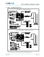
see fig #2
Figure 3
– The MTIC should be switched off prior to altering the DIP switch settings.
SW
Function
Position
Description
A
Timer
►
►
Instantaneous actuation when level reaches sensor.
B
A
Timer
►
◄
Time delay on actuation approx. 5 seconds.
B
A
Timer
◄
►
Time delay on actuation approx. 10 seconds.
B
A
Timer
◄
◄
Time delay on actuation approx. 15 seconds
.
B
C
Extr
a low sensitivity 1KΩ
◄
◄
For concentrates such as acids, minerals, alkalis leaving
residue.
D
C
Normal low sensitivity
4KΩ
◄
►
Acids, alkalis, diluted brine, sea water.
D
C
Normal sensitivity 20KΩ
►
◄
Sullage, sewage effluent, town water.
D
C
►
►
Effluent and processes with oil contaminants, purified
water.
D
NOTE:
Conductance may vary from liquid type as described above. Adjust sensitivity as
required.


