MTIC Installation & Operation Manual
Page 10 of 18
MTIC Manual R6
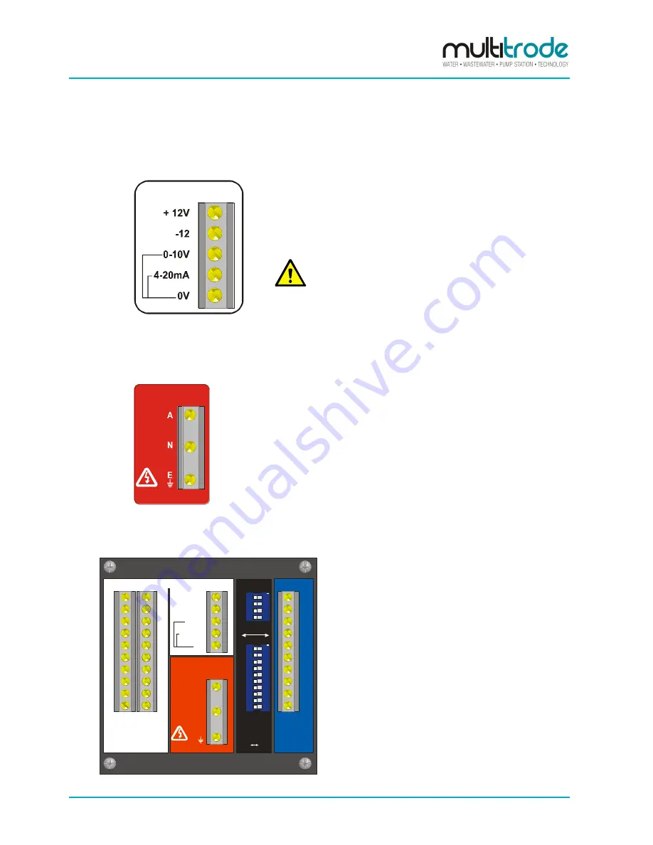
2.5 Analog Output
This section is
white
in colour on the rear panel.
see fig #1
Figure 7
– Analog Output
The analogue outputs supply 4-20mA and 0-10V.
It must be noted that these outputs are non-isolated. Various
wiring configurations allow for 4-20mA loads up to 940 W.
CAUTION:
Under no circumstances connect 0 volts to mains earth.
2.6 Power Supply Terminals & Ratings Label
This section is
red
in colour on the rear panel.
MAINS POWER
240VAC
50/60Hz
Figure 8
– Power Supply Terminals
A ratings label is located above the supply terminals and power
is supplied through these terminals.
Active, Neutral and Earth are connected to their respective
terminals as marked.
3
Installation & Power-Up
PROBE
INPUTS
MAINS POWER
OUTPUTS
A
N
E
240VAC
50/60Hz
1
2
3
4
5
6
7
8
9
10
1
2
3
4
5
6
7
8
9
10
+ 12V
-12
0-10V
4-20mA
0V
see fig #3
see fig #1
NO NC
SELECT
FUNCTION
A
B
C
D
1
2
3
4
5
6
7
8
9
10
see fig #2
1
2
3
4
5
6
7
8
9
10
ON
1
2
3
4
ON
see fig #1
MTIC
S/N: ___________
Figure 9 - MTIC Indicator Controller Back Panel
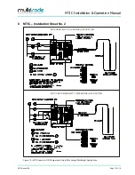
Before attempting to install the MTIC
read this
section thoroughly
.
Check the power rating label above the power input
terminals (see drawing below). Make sure that the
power supply configuration is compatible with the
installation being carried out.