MTIC Installation & Operation Manual
MTIC Manual R6
Page 13 of 18
5.2 Output Relays
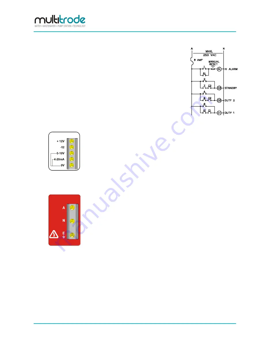
All output relays should be protected by an 8 amp (max.) fuse.
There are 10 isolated relay outputs which can be selected N/O or N/C via
DIP switches 1 to 10. Select outputs which coincide with the desired level
on the probe where control is required. As the MTIC does not latch each
central point, this needs to be achieved using "hold in" contacts on the
contactor, as per following example:
Hi Alarm on at 1
Standby on at 2, off at 7
Duty 2 on at 4, off at 8
Duty 1 on at 6, off at 10
Figure 12
– Output Relays
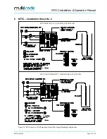
5.3 Analog Output
This section is
white
in colour on the rear panel.
see fig #1
Figure 13
– Analog Output
As can be seen by the diagram the MTIC can drive into a
maximum 940W if connected as shown.
It should be noted that the analogue output is non-isolated and
in certain circumstances will require a loop isolator.
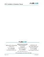
5.4 Power Connection
This section is
red
in colour on the rear panel.
MAINS POWER
240VAC
50/60Hz
Figure 14
– Power Connections
Prior to connecting the power to the controller, the following
checks should be performed:
1. Check the controller voltage rating to ensure compatibility.
2. Check that the function DIP switches have been set for the
correct defaults. Connect as follows:-
A = Active
N = Neutral
E = Earth


