MTIC Installation & Operation Manual
MTIC Manual R6
Page 7 of 18
1.1 Front Panel
POWER ON
1
2
3
4
5
6
7
8
9
10
LAG
STANDBY
LEAD
PUMP OFF
LO ALARM
HI ALARM
M U LT IT R O D E IN D IC AT O R C O N T R O L L E R
IC
MT
MT
IC
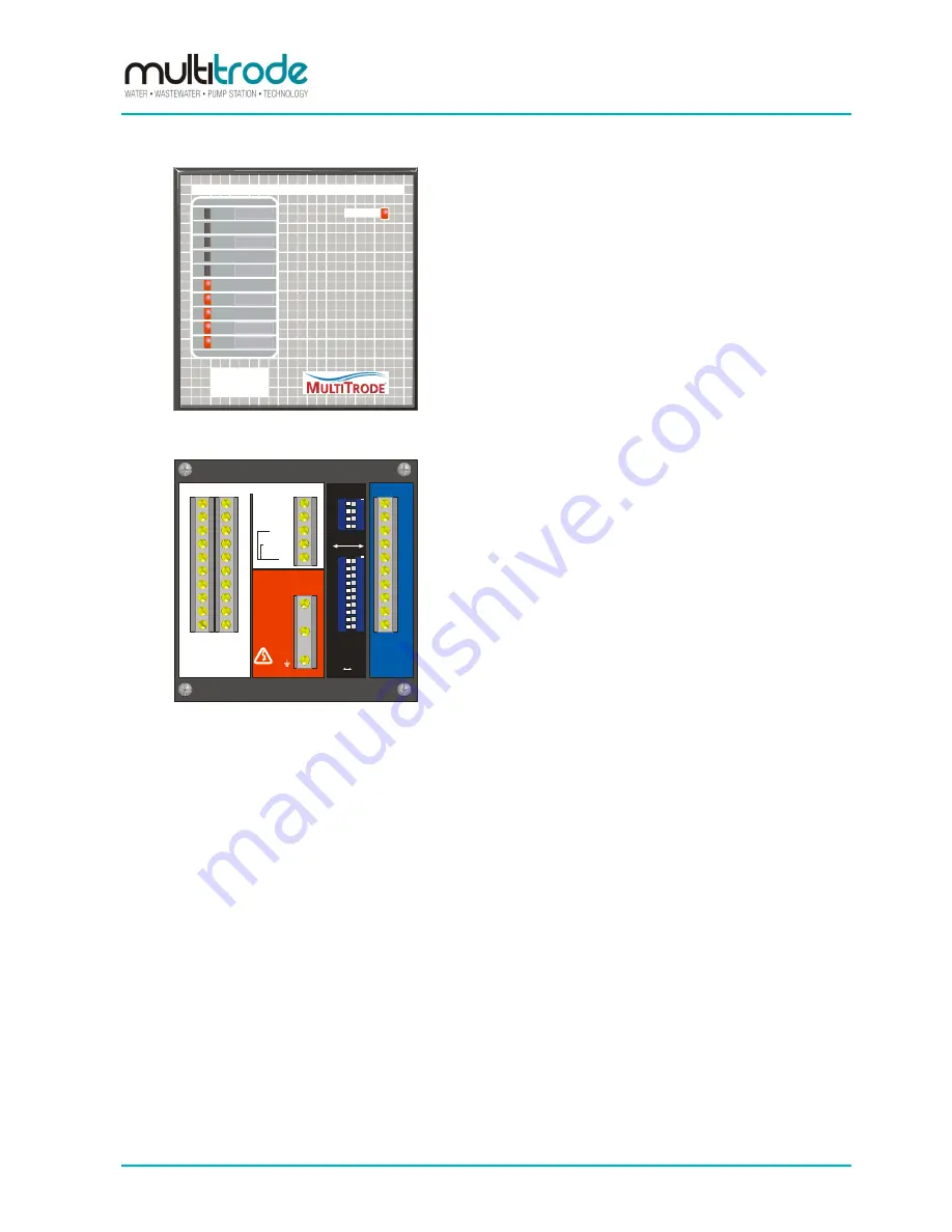
Figure 1 - MTIC Indicator Controller Front Panel
The MTIC has 11 LED
’s. The bar graph on the left-
hand side indicates level, whilst the green LED in the
upper right-hand corner indicates power availability.
There is a slot located next to the bar-graph, that is
used for the placement of labels to indicate at what
levels pumps and alarms operate. Up to 10 labels can
be placed here.
PROBE
INPUTS
MAINS POWER
OUTPUTS
A
N
E
240VAC
50/60Hz
1
2
3
4
5
6
7
8
9
10
1
2
3
4
5
6
7
8
9
10
+ 12V
-12
0-10V
4-20mA
0V
see fig #3
see fig #1
NO NC
SELECT
FUNCTION
A
B
C
D
1
2
3
4
5
6
7
8
9
10
see fig #2
1
2
3
4
5
6
7
8
9
10
ON
1
2
3
4
ON
see fig #1
MTIC
S/N: ___________
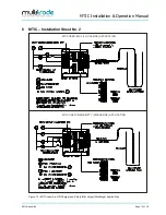
Figure 2 - MTIC Indicator Controller Back Panel
The MTIC rear panel (see Figure 2), contains the
terminals, as well as function DIP switches, used to
preset the unit's basic operations.
This section describes the function of each terminal
and DIP switch.


