background image

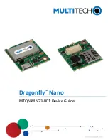
DRAGONFLYTM NANO DEVICE GUIDE

2

Dragonfly

Nano MTQN-MNG3-B01 Device Guide

Dragonfly

TM

Nano Device Guide

Models: MTQN-MNG3-B01

Part Number: S000712 Rev. 1.6

Copyright

This publication may not be reproduced, in whole or in part, without the specific and express prior written permission signed by an executive officer of
Multi-Tech Systems, Inc. All rights reserved.

Copyright © 2021 by Multi-Tech Systems, Inc.

Multi-Tech Systems, Inc. makes no representations or warranties, whether express, implied or by estoppels, with respect to the content, information,
material and recommendations herein and specifically disclaims any implied warranties of merchantability, fitness for any particular purpose and non-
infringement.

Multi-Tech Systems, Inc. reserves the right to revise this publication and to make changes from time to time in the content hereof without obligation of
Multi-Tech Systems, Inc. to notify any person or organization of such revisions or changes.

Trademarks and Registered Trademarks

MultiTech, and the MultiTech logo, MultiConnect, and Dragonfly are trademarks or registered trademarks of Multi-Tech Systems, Inc. All other products
and technologies are the trademarks or registered trademarks of their respective holders.

Legal Notices

The MultiTech products are not designed, manufactured or intended for use, and should not be used, or sold or re-sold for use, in connection with
applications requiring fail-safe performance or in applications where the failure of the products would reasonably be expected to result in personal injury or
death, significant property damage, or serious physical or environmental damage. Examples of such use include life support machines or other life
preserving medical devices or systems, air traffic control or aircraft navigation or communications systems, control equipment for nuclear facilities, or
missile, nuclear, biological or chemical weapons or other military applications (“Restricted Applications”). Use of the products in such Restricted
Applications is at the user’s sole risk and liability.

MULTITECH DOES NOT WARRANT THAT THE TRANSMISSION OF DATA BY A PRODUCT OVER A CELLULAR COMMUNICATIONS NETWORK WILL BE
UNINTERRUPTED, TIMELY, SECURE OR ERROR FREE, NOR DOES MULTITECH WARRANT ANY CONNECTION OR ACCESSIBILITY TO ANY CELLULAR
COMMUNICATIONS NETWORK. MULTITECH WILL HAVE NO LIABILITY FOR ANY LOSSES, DAMAGES, OBLIGATIONS, PENALTIES, DEFICIENCIES, LIABILITIES,
COSTS OR EXPENSES (INCLUDING WITHOUT LIMITATION REASONABLE ATTORNEYS FEES) RELATED TO TEMPORARY INABILITY TO ACCESS A CELLULAR
COMMUNICATIONS NETWORK USING THE PRODUCTS.

The MultiTech products and the final application of the MultiTech products should be thoroughly tested to ensure the functionality of the MultiTech
products as used in the final application. The designer, manufacturer and reseller has the sole responsibility of ensuring that any end user product into
which the MultiTech product is integrated operates as intended and meets its requirements or the requirements of its direct or indirect customers.
MultiTech has no responsibility whatsoever for the integration, configuration, testing, validation, verification, installation, upgrade, support or maintenance
of such end user product, or for any liabilities, damages, costs or expenses associated therewith, except to the extent agreed upon in a signed written
document. To the extent MultiTech provides any comments or suggested changes related to the application of its products, such comments or suggested
changes is performed only as a courtesy and without any representation or warranty whatsoever.

Contacting MultiTech

Country

Sales

Support

Europe, Middle East,
Africa:

[email protected]

+(44) 118 959 7774

[email protected]

+(44) 118 959 7774

U.S., Canada, all
others:

[email protected]

(800) 328-9717 or (763) 785-
3500

[email protected]

(800) 972-2439 or (763) 717-
5863

Website

www.multitech.com

Knowledge Base

For immediate access to support information and resolutions for MultiTech products, visit

http://www.multitech.com/kb.go

.

Support Portal

To create an account and submit a support case directly to our technical support team, visit:

https://support.multitech.com

.

Warranty

To read the warranty statement for your product, visit

https://www.multitech.com/legal/warranty

.

World Headquarters

Multi-Tech Systems, Inc.

2205 Woodale Drive, Mounds View, MN 55112

Summary of Contents for 94558240LF

Page 1: ...Dragonfly Nano MTQN MNG3 B01 Device Guide...

Page 2: ...RANT THAT THE TRANSMISSION OF DATA BY A PRODUCT OVER A CELLULAR COMMUNICATIONS NETWORK WILL BE UNINTERRUPTED TIMELY SECURE OR ERROR FREE NOR DOES MULTITECH WARRANT ANY CONNECTION OR ACCESSIBILITY TO A...

Page 3: ...Operating Conditions 10 Absolute Maximum Ratings 10 Nominal Ratings 11 Power Draw 12 Chapter 4 Antennas 13 Antenna 13 Antenna Specifications 13 Chapter 5 Safety Information 14 Handling Precautions 14...

Page 4: ...tatement 26 Registration of Substances 26 Information on HS TS Substances According to Chinese Standards in Chinese 27 Information on HS TS Substances According to Chinese Standards 28 Chapter 10 Usin...

Page 5: ...de Provides information for using the developer board with the MTQN S000610 ST Microcontroller Data Sheet Data sheet for processor STM32L471QG https www st com en microcontrollers stm32l471qg htm l 02...

Page 6: ...MECHANICAL DRAWINGS 6 Dragonfly Nano MTQN MNG3 B01 Device Guide Chapter 2 Mechanical Drawings MTQN MNG3 B01...

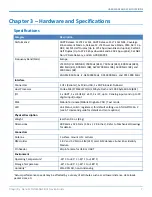
Page 7: ...Board Host Processor Cortex M4 STM32L471QG 1 Mbyte Flash and 128 Kbyte SRAM B01 I O 1 x UART 1 x HS USB 2 x SPI 2 x I2C up to 9 analog inputs and up to 29 digital input output SMS Mobile Terminate Mob...

Page 8: ...l Drawings for more information Here are some standoffs that can be used with this product Recommended Parts Manufacturer Part Part Number PEM Penn Engineering Manufacturing Surface Mount Standoff SMT...

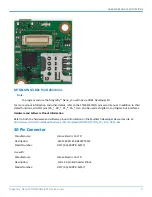
Page 9: ..._ can also be used as Digital In and Digital Out interfaces Hardware and Software Pinout Information Refer to both the hardware and software pinout information on the Multitech Developer Resources sit...

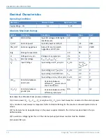
Page 10: ...n VDD VDDA VDDIO2 4 03 4 V Input voltage on TT_xx pins VSS 0 3 4 0 V Input voltage on BOOT0 pin VSS 9 0 V Input voltage on any other pins VSS 0 3 4 0 V VDDx Variations between power pins Variations be...

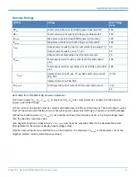
Page 11: ...ected current on PA4 PA5 IINJ PIN Total injected current sum of all I Os and control pins 5 5 0 25 Data taken from STM32L471QG processor datasheet 1 All main power VDD VDDA VDDIO2 VBAT and ground VSS...

Page 12: ...Card External DC Supply used GSM850 7 5 28 N A N A N A 5 Volts with Unit In Dev Card LTE 8 5 42 180 680 0 245 5 Volts USB only no Dev card LTE 292 58 238 864 0 281 3 3 Volts with Unit in Dev Card Ext...

Page 13: ...a with SMA Male Connector Model Number GY115IE002 001 MultiTech ordering information Model Quantity ANLTE4 1HRA 1 ANLTE4 2HRA 2 ANLTE4 10HRA 10 ANLTE4 50HRA 50 Antenna Specifications Category Descript...

Page 14: ...around gasoline or diesel fuel pumps and before filling your vehicle with fuel Switch OFF your wireless device in hospitals and any other place where medical equipment may be in use S curit relative...

Page 15: ...rillators are safe from cellular device EMI The FDA continues to monitor cellular devices for interactions with other medical devices If harmful interference occurs the FDA will assess the interferenc...

Page 16: ...specifically approved for such use The device may cause sparks Sparks in explosive areas could cause explosion or fire and may result in property damage severe injury and or death Do not expose your...

Page 17: ...platform and operating system for embedded devices using the ARM Cortex M microcontrollers The Mbed website provides free software libraries hardware designs and online tools for rapid prototyping of...

Page 18: ...stm32l471qg html Communications Flow MTQN MNG3 B01 The MTQN MNG3 B01 provides full UART from the cellular radio to the processor as well as the user application Model B01 provides a direct USB interf...

Page 19: ...nector to avoid enumeration or power issues Use a high speed USB cable that is as short as possible Use a well shielded cable with at least 24 AWG wire pair for power ground and 28 AWG wire pair for d...

Page 20: ...Down The Cellular Radio section 2 PSM mode AT CPSMS command 3 eDRX AT CEDRXS command 4 Device functionality AT CEDRXS command Power to Cellular Radio After power down RADIO_PWR can be configured as a...

Page 21: ...network and application This includes setting the applicable MNO profile based on carrier RAT type of technology you wish to use such as Cat M1 and LTE bands intended for the application device within...

Page 22: ...arately before UBANDMASK AT CFUN 0 AT UMNOPROF 0 AT CFUN 15 AT CFUN 0 AT CGDCONT AT UBANDMASK AT CFUN 15 To configure the supported radio bands Use the UBANDMASK command if your MNO is not listed by t...

Page 23: ...on The MultiTech model identification allows the carrier to verify the modem as one of its approved models This information is located on the modem s label below the bar code Example Labels Note Actua...

Page 24: ...rective 2011 65 EU on the restriction of the use of certain hazardous substances in electrical and electronic equipment and Council Directive 2014 53 EU on radio equipment and telecommunications termi...

Page 25: ...obliged to finance the costs of recovery from municipal collection points reuse and recycling of specified percentages per the WEEE requirements Instructions for Disposal of WEEE by Users in the Europ...

Page 26: ...halate DEHP 1000 ppm Benzyl butyl phthalate BBP 1000 ppm Dibutyl phthalate DBP 1000 ppm Diisobutyl phthalate DIBP 1000 ppm Environmental considerations Moisture Sensitivity Level MSL 1 Maximum Solderi...

Page 27: ...Chinese MII EIP 39 RoHS Multi Tech Systems Inc TS HS PB Hg CD CR6 PBB PBDE O O O O O O X O O O O O X O O O O O O O O O O O O O O O O O ICs O O O O O O O O O O O O X O O O O O O O O O O O O O O O O O...

Page 28: ...ed Biphenyl PBB Polybrominat ed Diphenyl Ether PBDE Printed Circuit Boards O O O O O O Resistors X O O O O O Capacitors X O O O O O Ferrite Beads O O O O O O Relays Opticals O O O O O O ICs O O O O O...

Page 29: ...e appropriate drivers are installed can cause the connection to fail To install Connection Manager and the device drivers 1 Go to https www multitech com support connection manager 2 Click Connection...

Page 30: ...r computer if prompted by Windows If using a USB device you can connect the device to the carrier s network with Connection Manager Refer to Connecting a Device If using a serial device you need to se...

Page 31: ...cting another model may cause your device to work incorrectly or fail f Select your COM port then click Next g Click Finish h Go to Device Manager Modems and confirm that the device is added 6 To veri...

Page 32: ...pings to a host check Enable keep alive and enter the IP address or host name to ping in the Host to ping box For example you can enter the host name google com or IP address 8 8 8 8 If the keep aliv...

Page 33: ...strength percentage and bars The statistics on connection speeds and traffic are available only during a current connection session Note For serial modems the signal strength is available only when th...

Page 34: ...following Status of device connection Searching Connecting Connected Disconnecting or Disconnected The action button which changes according to the current device connection status Detect Connect or D...

Page 35: ...Connection tab The Connection tab displays the following The carrier provided connection settings The Enable keep alive check box Check this box to monitor connectivity to the Internet Check Enable ke...

Page 36: ...onnected to the PC and that the correct USB cable is in use Connection Manager is not working and a device connected to the computer is not detected Connection Manager cannot detect a connected device...

Page 37: ...verview 29 Settings tab 34 Terminal tab 34 troubleshooting 36 uninstalling 33 D device connecting to carrier s network with Connection Manager 32 device drivers installation for use with Connection Ma...

Reviews: