5 of 9
Part Number 020006402 12/2014
Air Compressor Kits
Aio PuIm & Ttak wirh Chtage-pveo Vtlve & DuIm Vtlve Kir — P.N. 00212145 (220V),
P.N. 00214971 (220V)
These instructions cover the installation of the 220V/50Hz
Multiplex Air Pump kit. This kit is designed to be used
with Model 37KX and Model 44KX. The air pump must be
mounted to the support stand with a minimum of a 6-inch
clearance.
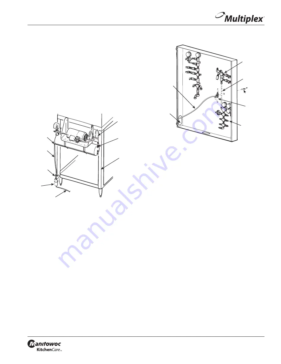
1. Mount air compressor mounting channel to left side of
stand in the third hole down with two 1/4-20 nuts and
screws provided with kit. (See figure below)
2. Install pump/tank assembly to stand and mounting
channel with four 1/4-20 nuts and screws provided
with kit. (See figure below)
1/4" ID Tube
(Use 3 Ft.)
Air Pump Tank
Compression
Elbow
Shutoff
Valve
Air Compressor
Mounting
Channel
8 ft. (2.44 m) Length" of
Tubing to Floor Drain
Pump Tank
Assembly
Stand
Dump Valve
asrtlltripa
NSTALLATON OF MODEL 37KX REFRGERATON UNT
1. Shut off main CO
2
supply to refrigeration unit.
2. Open the CO
2
control panel door on the refrigeration
unit and locate the 3/8" O.D. (9.5 mm) white
polyethylene tubing that is routed between the
carbonator tank CO
2
supply manifold and the syrup
tank CO
2
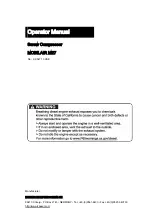
supply manifold (see figure below). Remove
and discard this section of tubing.
12' x 114"
(3.86 m x 6.35 mm)
Eva Tubing
To Outlet
Fitting of Air
Pump Tank
Carbonator
Tank CO
2
Supply
Manifold
Remove and
Discard
Syrup Tank
CO
2
Supply
Manifold
Air/CO
2
Change-over Valve
Retaining Ring,
Handle, and Screw
Mpdel 37KX Mtaifplds
3. Locate the air/CO
2
change-over valve supplied with
the air pump installation kit (P.N. 212508 Provided with
Stand). Remove the change-over valve handle, screw,
and retainer ring. Install the change-over valve in the
hole provided in the control panel marked “Air/CO
2
Change-over Valve”. Replace the retainer ring, valve
handle, and screw. (See figure above)
4. Attach the upper 3/8" O.D. (9.5 mm) white polyethylene
tubing of the CO
2
change-over valve to the carbonator
tank CO
2
supply manifold. Attach the lower 3/8" O.D.
(9.5 mm) white polyethylene tubing of the CO
2
change-
over valve to the syrup tank CO
2
supply manifold. Use
compression nuts supplied with kit. (See figure above)
NOTE: Tum air/CO
2
change-over valve handle to the “CO
2
”
position.
5. Locate the 12' x 1/4" EVA (3.66 meters x 6.35 mm)
tubing supplied with air compressor. Attach the end
of this line assembly with the swivel nut to the outlet
fitting of the air compressor tank. Neatly route tubing
under the stand top, up through the opening in lower
right end of control panel and attach the opposite end
of this line assembly to the 1/4" (6.35 mm) barb elbow
of the air/CO
2
change-over valve previously installed in
the control panel. Trim excess line as necessary. Use two
tab clamps to hold tube on stem. (See figure above)
6. Locate the dump valve supplied with air compressor.
Mount the dump valve with #10-32 self-tapping screws
provided with kit to lower left cross channel of support
stand. Use holes provided in channel. (See Installation
figure)


