Mueller Model D Fre-Heater Installation and Operation Manual
Effective March 1, 1993
Part No. 8800430
Revised November 6, 2019
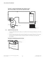
FIGURE 14: TYPICAL HEAT PUMP REFRIGERANT PIPING DIAGRAM
2.10
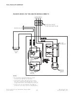
ELECTRICAL CONNECTIONS FOR MODEL “DE” FRE-HEATER
A separate 30 A, 240 V branch circuit must be installed by a qualified electrician for heating element operation. In
addition, a 24 V line from the condensing unit circuit must be connected to the regulating/limiting thermostats and
solenoid. All wiring must comply with the National Electrical Code and any local codes.
The electric heating element is prewired to the conduit box in the top of the Fre-Heater. Supply circuit connections
should be made to the red and black wires in this compartment. The supply circuit ground must be connected
to the green grounding lug in the conduit box to protect the user from possible electrical shock. Use only copper
conductors for these connections. See Figure 15 for a wiring schematic.
A separate circuit for regulating the refrigerant heated water temperature must originate from the condensing unit
power supply circuit. It should be protected with a 5 A in-line fuse. This circuit connects the thermostats on the
water heater in series with the water dump valve (or the optional hot gas bypass solenoid). Class I wiring should be
used in the circuit. See Figure 15 for connection details.
DANGER: When installing or servicing electrical components on this unit, turn both the heating element
and condensing unit power supplies off to avoid the possibility of electrical shock.
IMPORTANT: The tank must be full of water before the power is turned on. The heating element will be
damaged if it is energized even for a short period of time while the tank is empty.
15
Mueller
Fre-Heater
Suction
Line
Heat
Reclaim
Valve
Heat/Cool
Valve
Outdoor Coil
Indoor Coil
Check Valve
Compressor


