Mueller Model D Fre-Heater Installation and Operation Manual
Effective March 1, 1993
Part No. 8800430
Revised November 6, 2019
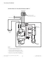
FIGURE 12: TYPICAL DUAL CONDENSING UNIT PIPING
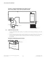
FIGURE 13: FRE-HEATER LOCATION WITH HOT GAS DEFROST VALVE,
OIL SEPARATOR, AND/OR DISCHARGE MUFFLER IN SYSTEM
14
Condenser
Mueller
Fre-Heater
Condenser
Discharge
Line
Mueller
Fre-Heater
Condenser
Discharge
Muffler
To Receiver
Compressor
Oil Separator
Suction Line
Oil Return Line
Hot Gas Defrost Valve
This piping configuration should
only be used for condensing units
within the range of the per circuit
ratings, as shown in Table 1.


