Mueller Model D Fre-Heater Installation and Operation Manual
Effective March 1, 1993
Part No. 8800430
Revised November 6, 2019
3.1 SOLENOID VALVE INSTALLATION
The three-way heat reclaim valve (Mueller Part Nos. 8827286 and 8827284) information is as follows:
• Refrigerant must be recovered before cutting the refrigerant lines to install the three-way heat reclaim valve.
• Accepted refrigeration practices must be used while installing the valve. These practices are of common
knowledge to experienced refrigeration service technicians, and only an experienced service technician should
undertake the installation of the solenoid valve.
• The valve’s installation location should be as close as practical to the refrigeration compressor.
• The valve should be installed in a vertical position, coil up, and supported by hangers.
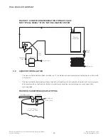
• A check valve must be installed in the refrigerant line between the Mueller Fre-Heater and the tee, as shown in
Figure 17.
• Suggested refrigeration piping of the valve in a typical Model “D” or “DE” Fre-Heater system is illustrated in
Figure 17. See Table 4 for check valve sizing.
• Piped in the suggested manner, the valve coil will be energized when water heating is needed. When the hot
water demand is satisfied, the valve will be de-energized.
TABLE 2: THREE-WAY HEAT RECLAIM VALVES
FIGURE 16: THREE-WAY HEAT RECLAIM VALVES
18
Section 3.0 – Water Temperature Limit and Three-Way Heat Reclaim Valve
Mueller
Part No.
MOPD
(psi)
Maximum Rated
Pressure (psi)
Standard Coil Ratings
Port Size
Connection
Size
Volts/Cycles
Watts
8827286
300
500
24/50/60
15
5
⁄
8
"
5
⁄
8
" ODF
8827284
300
500
24/50/60
15
1
1
⁄
4
"
1
3
⁄
8
" ODF
Part No. 8827286
Part No. 8827284


