background image

8.12 Starting Equipment

8.12.1 Air starter – Manual operation

DANGER

Rotating and moving engine parts.
Risk of crushing, danger of parts of the body being caught or pulled in!
• Before cranking the engine with starter system, make sure that there are no persons in the engine's

danger zone.

WARNING

High level of engine noise when the engine is running.
Risk of damage to hearing!
• Wear ear protectors.

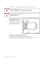
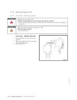
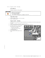
Air starter – Manual operation

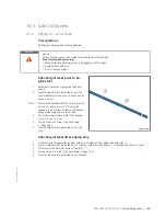
1.

Press pushbutton for manual start (arrow)
and hold.

2.

Allow compressed air to enter the starter un-
til the engine fires evenly.

3.

Release pushbutton.

104 | Starting Equipment | M015565/03E 2016-02

TIM-ID: 0000006076 - 006

Summary of Contents for 20V4000GX2

Page 1: ...Operating Instructions Diesel Engine 20V4000Gx2 M015565 03E...

Page 2: ...kW cyl 50 Hz 3C restricted operation ICXN 20V4000G62 137 0 kW cyl 60 Hz 3C restricted operation ICXN 20V4000G62 133 5 kW cyl 50 Hz 3D emergency power fuel stop power IFN 20V4000G62 150 5 kW cyl 60 Hz...

Page 3: ...ng the engine into operation after scheduled out of service period 44 5 3 Engine Starting in manual mode test run 45 5 4 Starting the engine in emergency situations override mode 46 5 5 Operational mo...

Page 4: ...lling 114 8 15 5 Engine coolant pump Relief bore check 116 8 16 Low Temperature Circuit 117 8 16 1 Charge air coolant Level check 117 8 16 2 Charge air coolant Change 118 8 16 3 Charge air coolant dra...

Page 5: ...cesses that might affect the emission characteristics of the product are prohibited by emission regulations Emission control units systems may only be maintained ex changed or repaired if the componen...

Page 6: ...particular with regard to the specified tightening torques With the exclusive use of technical personnel trained in commissioning operation maintenance and re pair By contracting only workshops autho...

Page 7: ...be instructed repeatedly Personnel requirements All work on the product shall be carried out by trained and qualified personnel only Training at the Training Center of the manufacturer Technical perso...

Page 8: ...e product into operation make sure that all control and display instruments as well as the signaling and alarm systems work properly Smoking is prohibited in the area of the product Safety regulations...

Page 9: ...Follow the applicable warning instructions pertaining to such devices M015565 03E 2016 02 Safety 9 TIM ID 0000040533 012...

Page 10: ...V belts must not be painted They may only be installed after painting the engine or must be covered before painting work is carried out The following applies to starters with copper beryllium alloy p...

Page 11: ...g in its vicinity Before starting welding work Switch off the power supply master switch Disconnect the battery cables or actuate the battery isolating switch Separate the electrical ground of electro...

Page 12: ...h sharp edges Chafing on components Contact with hot surfaces Do not secure cables on lines carrying fluids Do not use cable straps to secure cables Always use connector pliers to tighten union nuts o...

Page 13: ...ully with its handling Noise Noise can lead to an increased risk of accidents if acoustic signals warning shouts or sounds indicating dan ger are drowned Wear ear protectors in workplaces with a sound...

Page 14: ...rrying out painting work outside the spray stands provided with fume extraction systems ensure that the area is well ventilated Make sure that neighboring work areas are not adversely affected There m...

Page 15: ...n NOTICE In the event of a situation involving potentially adverse effects on the product Consequences Material damage Remedial action Additional product information Warning notices 1 This manual with...

Page 16: ...or 6 Raise and lower the engine generator slowly Do not allow hoist slings or chains to contact the engine generator or any of their component parts Adjust lifting gear as necessary 7 For special pack...

Page 17: ...lifting devices and appliances Never stand beneath a suspended load 1 Max admissible diagonal pull 10 2 Center of gravity Take note of the engine center of gravity See Installation Arrangement drawin...

Page 18: ...be reinstalled on both engine sides accord ing to the instructions 3 If the engine is to be moved together with the generator the transport locking device for the generator must also be installed 4 A...

Page 19: ...the ring gear 4 Screw in screw 1 in bores of retainer 3 until retainer 3 is locked in position Note Screw 1 must be tightened stepwise and alternately on both sides of the flywheel housing 5 Tighten...

Page 20: ...ys use the screws supplied with the or removed from the guard plates and engine mounting brackets to secure them on the en gine 1 Install engine mounting brackets 2 on both sides with guard plates 1 w...

Page 21: ...gnated in accordance with DIN ISO 1204 as viewed from driving end 4 For cylinder designation in accordance with DIN ISO 1204 the letter Ax refers to the cylinders on the left hand side of the engine 1...

Page 22: ...ylinder 16 Cylinder head 17 Crankcase and add on com ponents 18 Fuel prefilter 19 HP fuel pump 20 Gear train 21 Lube oil filter 22 Crank drive 23 Battery charging generator 24 Coolant system KGS Free...

Page 23: ...5 25 Charge air coolant temperature C 55 55 Raw water inlet temperature C Barometric pressure mbar 1000 1000 Site altitude above sea level m 100 100 Power related data power ratings are net brake powe...

Page 24: ...ndividual cylinder heads X X Cylinder liners wet replaceable X X Number of inlet valves per cylinder 2 2 Number of exhaust valves per cylinder 2 2 Standard housing connecting flange engine main PTO SA...

Page 25: ...rm R bar 4 5 4 5 Lube oil pressure before engine shutdown L bar 4 0 4 0 Fuel system Engine model Unit 20V4000 G62 20V4000 G82 Fuel pressure at engine inlet connection during engine start min admissibl...

Page 26: ...rating inclinations L Liter 340 340 Weight Engine model Unit 20V4000 G62 20V4000 G82 Engine weight dry basic engine configuration in accord ance with scope of delivery specifications R kg 9450 9450 So...

Page 27: ...20V4000 G62 20V4000 G42 20V4000 G82 Application group 3B 3B 3B 3B 3B 3B Intake air tempera ture C 25 25 25 25 25 25 Charge air coolant temperature C 55 55 55 55 55 55 Raw water inlet tem perature C B...

Page 28: ...ting method Four stroke cycle diesel single action X X X X X X Combustion method direct fuel injection X X X X X X Cooling method con ditioned water X X X X X X Direction of rotation c c w facing driv...

Page 29: ...ooling equipment A C 95 95 95 95 95 95 Coolant temperature after engine warning R C 97 97 97 97 97 97 Coolant temperature after engine shut down L C 99 99 99 99 99 99 Coolant antifreeze content max pe...

Page 30: ...ure be fore engine shut down L bar 4 0 4 0 4 0 4 0 4 0 4 0 Fuel system Engine model Unit 20V4000 G22 20V4000 G62 20V4000 G22 20V4000 G62 20V4000 G42 20V4000 G82 Fuel pressure at en gine inlet connecti...

Page 31: ...245 245 Oil pan capacity dip stick mark max standard oil system design max operat ing inclinations L Liter 340 340 340 340 340 340 Weight Engine model Unit 20V4000 G22 20V4000 G62 20V4000 G22 20V4000...

Page 32: ...coolant temperature C 55 55 55 55 Raw water inlet temperature C Barometric pressure mbar 1000 1000 1000 1000 Site altitude above sea level m 100 100 100 100 Power related data power ratings are net br...

Page 33: ...1 89 81 89 81 Compression ratio 15 5 15 5 15 5 15 5 Cylinder heads Individual cylinder heads X X X X Cylinder liners wet replaceable X X X X Number of inlet valves per cylinder 2 2 2 2 Number of exhau...

Page 34: ...ating temperature be fore engine from R C 85 85 85 85 Lube oil operating temperature be fore engine to R C 95 95 95 95 Lube oil temperature before engine alarm R C 95 95 95 95 Lube oil temperature bef...

Page 35: ...andard oil system design max operating inclinations R Liter 340 340 340 340 Oil pan capacity dipstick mark min standard oil system design max operating inclinations L Liter 245 245 245 245 Oil pan cap...

Page 36: ...perature C 55 55 55 55 Raw water inlet temperature C Barometric pressure mbar 1000 1000 1000 1000 Site altitude above sea level m 100 100 100 100 Power related data power ratings are net brake power a...

Page 37: ...1 89 81 89 81 Compression ratio 15 5 15 5 15 5 15 5 Cylinder heads Individual cylinder heads X X X X Cylinder liners wet replaceable X X X X Number of inlet valves per cylinder 2 2 2 2 Number of exhau...

Page 38: ...ating temperature be fore engine from R C 85 85 86 86 Lube oil operating temperature be fore engine to R C 95 95 95 95 Lube oil temperature before engine alarm R C 95 95 95 95 Lube oil temperature bef...

Page 39: ...tandard oil system design max operating inclinations R Liter 340 340 340 340 Oil pan capacity dipstick mark min standard oil system design max operating inclinations L Liter 245 245 245 245 Oil pan ca...

Page 40: ...4 5 Final compression pressure Final compression pressure Final compression pressure at 120 rpm 24 bar to 28 bar 40 Technical Data M015565 03E 2016 02 TIM ID 0000002820 001...

Page 41: ...4 6 Firing order Number of cylinders Firing order 20 V A1 B5 A8 B7 A5 B2 A7 B10 A2 B3 A10 B6 A3 B4 A6 B9 A4 B1 A9 B8 M015565 03E 2016 02 Technical Data 41 TIM ID 0000035068 002...

Page 42: ...n engine dimensions Main engine dimensions Engine model Length A Width B Height C 20V4000G22 42 62 82 Approx 3520 mm Approx 1480 mm Approx 2390 mm 42 Technical Data M015565 03E 2016 02 TIM ID 00000021...

Page 43: ...er Fill with fuel Page 98 Fuel prefilter pressure gage Align adjustable pointer with position of pressure indicator Page 94 Fuel system Vent Page 91 Coolant circuit Change engine coolant if engine has...

Page 44: ...105 Cooling system Check engine coolant level Page 111 Check charge air coolant level Page 117 Cooling system Preheat coolant with preheating unit Fuel prefilter Drain Page 95 Monitoring equipment Ca...

Page 45: ...rting the engine Item Action Control cabinet control pan el etc depending on manu facturer If coolant temperature is 40 C with preheating system or 10 C 60 Hz generator without preheater 5 C 50 Hz gen...

Page 46: ...ontrol cabinet Actuate switch button for ECU override input Control cabinet Automatic starting procedure is performed any safety functions and alarms leading to engine shutdown are disregarded Engine...

Page 47: ...s in en gine operation are required Check for abnormal running noises and vibration HP pump Check relief bore Page 84 Fuel prefilter Check reading on differential pressure gage to ensure that maximum...

Page 48: ...After the generator breaker if provided has been opened allow the engine to cool down by running it idle for approx 5 minutes Preparing a pump drive diesel mechanical diesel electric Item Action Engin...

Page 49: ...from LOP Item Action Emergency stop pushbutton Press pushbutton Engine is stopped by disconnecting the power supply to the ECU Signaling e g by horn flashing lamp is tripped After emergency engine sto...

Page 50: ...o the coolant the engine room is not heated the coolant is not kept at a suitable temperature the antifreeze concentration is insufficient for the engine room tempera ture antifreeze concentration is...

Page 51: ...ectly at seals or electronic components such as connectors or ECUs Plant Cleaning 1 Carry out plant cleaning only in areas where an appropriate oil separator is provided environmental protec tion 2 Pr...

Page 52: ...ne for abnormal running noises exhaust color and vibrations Page 47 W0507 X Drain water and contaminants from fuel prefilter Page 47 W0508 X Check reading on differential pressure gage of fuel prefilt...

Page 53: ...nspection manufacturer s documentation Engine governor Plug in connections loose u Check plug in connections Page 130 Running gear blocked engine cannot be barred manually u Contact Service Engine tur...

Page 54: ...high Cause Corrective action Engine coolant treatment incorrect u Check MTU test kit Intercooler dirty u Contact Service Engine room Air intake temperature too high u Check fans and intake exhaust li...

Page 55: ...inder head piston rings or cylinder liner defective u Contact Service White exhaust gas Cause Corrective action Engine is not at operating temperature u Run engine to reach operating temperature Water...

Page 56: ...ontact Service to have the sensors actuators checked and if required re placed Fault code Alarm text Meaning Task 005 L1 T CHARGE AIR Charge air temperature too high 1st limit value Reduce power Chang...

Page 57: ...uel supply pressure too low 2nd limit value 1 Check fuel lines for leaks repair defec tive lines 2 Clean fuel prefilter Page 93 3 Flush fuel prefilter Page 96 4 Replace filter element of fuel prefilte...

Page 58: ...r ing point which is read via CAN bus 080 L Bin EXTERN 4 Alarm from external binary channel 4 Depending on the corresponding measur ing point which is read via CAN bus 081 RAIL LEAKAGE HP fuel system...

Page 59: ...ID Check sum error of hour meter data in IDM If fault occurs repeatedly Contact Service 106 ERR REC1 NOT VALID Check sum error of fault mem ory in EDM redundant data re cord 1 If fault occurs repeated...

Page 60: ...low Contact Service 147 AD TEST1 ECU DEFECT Electronic equipment defective automatic engine shutdown Contact Service 148 L1 AD TEST2 SUP PLY A D converter supply voltage too low Contact Service 149 AD...

Page 61: ...ensor defect charge air cool ant temperature 1 Check wiring 2 Contact Service 208 SD P CHARGE AIR Sensor defect charge air pres sure 1 Check wiring 2 Contact Service 211 SD P LUBE OIL Sensor defect lu...

Page 62: ...efective CAN P EXTERN 1 Contact Service 274 SD P EXTERN 2 External device defective CAN P EXTERN 2 Contact Service 275 SD EXT COOLANT LEVEL External coolant level monitor ing defective CAN Contact Ser...

Page 63: ...ault cylinder B6 If fault occurs repeatedly Contact Service 317 TIMING CYLINDER B7 Injection timing fault cylinder B7 If fault occurs repeatedly Contact Service 318 TIMING CYLINDER B8 Injection timing...

Page 64: ...ring to solenoid valve cylinder B4 Misfiring 1 Check wiring 2 Contact Service 335 WIRING CYLINDER B5 Faulty wiring to solenoid valve cylinder B5 Misfiring 1 Check wiring 2 Contact Service 336 WIRING C...

Page 65: ...on in wiring to sole noid valve cylinder A10 Misfiring 1 Check wiring 2 Contact Service 351 OPEN_LOAD CYL B1 Disconnection in wiring to sole noid valve cylinder B1 Misfiring 1 Check wiring 2 Contact S...

Page 66: ...2 Solenoid valve or wiring or en gine governor defective automatic engine shutdown 1 Check wiring 2 Try to re start the engine Page 45 3 Contact Service 365 STOP MV WIRING Solenoid valve wiring faulty...

Page 67: ...ing engine parts Risk of crushing danger of parts of the body being caught or pulled in Before barring the engine make sure that there are no persons in the engine s danger zone After finishing work o...

Page 68: ...to barring device 2 Note No resistance other than compression resist ance must be encountered 4 Rotate crankshaft in engine direction of rota tion Result If the resistance exceeds the normal com press...

Page 69: ...place and all tools are removed from the engine Cranking engine on starting sys tem 1 Disengage bayonet union nut 4 of connec tor X4 on Engine Control Unit using pipe gripping pliers 2 and disconnect...

Page 70: ...re are no persons in the engine s danger zone WARNING High level of engine noise when the engine is running Risk of damage to hearing Wear ear protectors Engine Test run 1 Start engine Page 45 2 Perfo...

Page 71: ...en top piston ring and bottom edge of carbon scraper ring First signs of marks left by top piston ring Bright mark on entire circumference Faultless even honing pattern First signs of marks left by lo...

Page 72: ...Depending on findings Do not take any action or carry out a further endoscopic examination as part of maintenance work or contact Service cylinder liner must be replaced Final steps 1 Install injector...

Page 73: ...ound the liner It appears rather darker within the honed struc ture in contrast to the bright metallic running surface The honing pattern is undis turbed Discolorations extend in stroke direction and...

Page 74: ...ation are similar A thorough inves tigation and compliance with the above evaluation criteria allow an unambiguous evaluation To avoid unnec essary disassembly work it is recommended that another insp...

Page 75: ...il Filter element Spare Parts Catalog O ring Spare Parts Catalog WARNING Hot oil Oil can contain combustion residues which are harmful to health Risk of injury and poisoning Wear protective clothing g...

Page 76: ...with new O ring 6 Tighten screws of cover tighten to specified torque using a torque wrench Name Size Type Lubricant Value Standard Screw Tightening torque Engine oil 6 Nm 2 Nm 7 Replace other oil sep...

Page 77: ...al 2 Undo screws 1 and remove with wash ers 2 3 Remove cylinder head cover 3 with gas ket 4 from cylinder head 4 Remove other cylinder head covers in the same way Installing cylinder head cover 1 Clea...

Page 78: ...nder head covers Page 77 2 Fill oil chambers of valve bridges with oil 3 Fill oil chambers of rocker arms and adjusting screws with oil 4 Install cylinder head covers Page 77 Lubricating valve gear fl...

Page 79: ...r gage Y20098771 1 Torque wrench 10 60 Nm F30452769 1 Torque wrench 60 320 Nm F30452768 1 Ring socket wrench F30039518 1 Engine oil Preparatory steps 1 Remove cylinder head cover Page 77 2 Install bar...

Page 80: ...ridge Note Not applicable for engines with flying valve bridge 1 Prior to adjusting valve clearance check valve bridge balance on all valve bridges 2 Use feeler gage to determine clearance be tween va...

Page 81: ...ith open end wrench and release locknut 2 2 Use feeler gage to determine clearance be tween valve bridge and rocker arm 3 Place one feeler gage of the determined val ue each between valve bridge and t...

Page 82: ...doing Name Size Type Lubricant Value Standard Nut M 16 x 1 5 Preload torque Engine oil 35 Nm 5 Nm 8 Recheck valve bridge balance Checking valve clearance at two crankshaft positions Item Explanation...

Page 83: ...arm 5 If the deviation from the specified value exceeds 0 1 mm adjust valve clearance Adjusting valve clearance 1 Release locknut 1 2 Insert feeler gage between valve bridge and rocker arm 3 Turn adj...

Page 84: ...Only run the engine at low power Keep away from the engine s danger zone WARNING High level of engine noise when the engine is running Risk of damage to hearing Wear ear protectors Checking HP fuel pu...

Page 85: ...r Replacement Special tools Material Spare parts Designation Use Part No Qty Injector Spare Parts Catalog Injector Replacement u Remove injector and install new one Page 86 M015565 03E 2016 02 Injecto...

Page 86: ...X00067260 1 Engine oil WARNING Fuels are combustible and explosive Risk of fire and explosion Avoid open flames electrical sparks and ignition sources Do not smoke Wear protective clothing protective...

Page 87: ...side is completed 1 Release the cable terminal threaded connec tion arrowed on the injector and remove ca ble terminals 2 Remove screw 2 and take off hold down clamp 1 3 Remove HP fuel line 5 4 Instal...

Page 88: ...nozzle retaining nut 3 Fit new O rings on injector and apply assem bly compound 4 Fit new sealing ring with assembly compound on injector pay attention to installation posi tion of sealing ring 5 Cle...

Page 89: ...fied initial tightening torque using a torque wrench Name Size Type Lubricant Value Standard Screw M12 Preload torque Engine oil 5 Nm to 10 Nm 13 Fit O rings 4 and 6 on HP fuel line 5 and coat with as...

Page 90: ...ench Name Size Type Lubricant Value Standard Union nut Tightening torque 120 Nm 10 Nm 18 Twist cable several times 19 Insert cable lugs arrowed underneath the screws on the injector and tighten screws...

Page 91: ...otective clothing protective gloves and safety glasses facial protection Venting LP fuel system 1 Loosen flushing return line of HP pump at connection 1 2 Unlock fuel priming pump 2 screw out han dle...

Page 92: ...l sparks and ignition sources Do not smoke Wear protective clothing protective gloves and safety glasses facial protection Fuel filter Replacement 1 Remove easy change filter using filter wrench 2 Cle...

Page 93: ...safety glasses facial protection Cleaning fuel prefilter 1 Close fuel supply 2 Remove nuts from filter head 3 Unscrew filter bowl and drain fuel into a suit able container 4 Remove securing nut for fi...

Page 94: ...r of dif ferential pressure gage 1 After installation of a new filter element Align adjustable pointer 2 with pressure indicat ing pointer 3 of pressure gage 1 2 Verify that differential pressure is w...

Page 95: ...ing fuel prefilter 1 Left filter cut in 2 Right filter cut in 1 Switch off filter to be drained 2 Open threaded vent plug 5 of the filter to be drained 3 Unlock drain valve 6 by pressing toggle and op...

Page 96: ...parks and ignition sources Do not smoke Wear protective clothing protective gloves and safety glasses facial protection WARNING Liquid or gaseous media e g fuel are poisonous Escaping vapors of highly...

Page 97: ...tered side flushing the filter deposits down wards out of the filter 4 Close threaded vent plug 5 and drain valve 6 Fuel prefilter Filling with fuel 1 Remove screws securing cover and take off cover 2...

Page 98: ...og Gasket Spare Parts Catalog WARNING Fuels are combustible and explosive Risk of fire and explosion Avoid open flames electrical sparks and ignition sources Do not smoke Wear protective clothing prot...

Page 99: ...ove spring housing 4 and filter ele ment 3 8 Insert new filter element 3 and spring hous ing 4 9 Fill filter housing with clean fuel 10 Place new gasket in cover 2 11 Fit cover with gasket and secure...

Page 100: ...direct air jet at people Always wear safety goggles face mask and ear defenders Intercooler Check water drain for coolant leakage and absence of restrictions 1 With the engine running check the drain...

Page 101: ...Material Spare parts Designation Use Part No Qty Air filter Spare Parts Catalog Air filter Replacement 1 Remove air filter and install new one Page 102 2 Reset signal ring of service indicator Page 1...

Page 102: ...lla tion 1 Loosen clamp 2 2 Remove air filter 1 and clamp 2 from con necting flange of intake housing 3 3 Verify that there are no objects in the flange of the intake housing 3 and clean it 4 Place ne...

Page 103: ...sabled Checking signal ring position 1 If the signal ring is completely visible in the control window 2 replace air filter Page 101 2 After installation of new filter press reset button 1 Result Engag...

Page 104: ...em make sure that there are no persons in the engine s danger zone WARNING High level of engine noise when the engine is running Risk of damage to hearing Wear ear protectors Air starter Manual operat...

Page 105: ...the oil level may be up to 2 cm above mark 1 This may be caused e g by oil from oil filters and heat ex changer flowing back into the oil pan 3 The oil level must reach mark 1 or exceed mark 1 by up...

Page 106: ...Avoid contact with skin Do not inhale oil vapor Oil change without semirotary hand pump Draining oil at drain plug s on oil pan 1 Provide a suitable container in which to collect the engine oil 2 Remo...

Page 107: ...l drain plug s with new sealing ring 5 Tighten drain screws 2 and 3 to specified torque using a torque wrench Name Size Type Lubricant Value Standard Screw M26 x 1 5 Tightening torque Engine oil 100 N...

Page 108: ...ing Wear protective clothing gloves and goggles safety mask Avoid contact with skin Do not inhale oil vapor Engine oil filter Replacement 1 Unscrew engine oil filter with filter wrench 2 Clean sealing...

Page 109: ...ring Spare Parts Catalog WARNING Hot oil Oil can contain combustion residues which are harmful to health Risk of injury and poisoning Wear protective clothing gloves and goggles safety mask Avoid con...

Page 110: ...rotor base 10 with sealing ring 9 13 Insert new filter sleeve 6 in rotor tube 7 with the smooth paper surface facing the wall 14 Check sealing ring 5 fit new one if necessa ry 15 Mount rotor cover 4 w...

Page 111: ...o turn cap counterclockwise and remove 3 Check engine coolant level engine coolant must be visible at bottom edge of cast in eye of filler neck Checking engine coolant level at remote cooler Note Engi...

Page 112: ...Material Spare parts Designation Use Part No Qty Coolant Engine coolant change 1 Drain engine coolant Page 113 2 Fill with engine coolant Page 114 112 Coolant Circuit General High Temperature Circuit...

Page 113: ...f filler neck on coolant expansion tank counterclockwise to first stop and allow pressure to escape 2 Continue to turn breather valve counterclockwise and remove 3 Draw off separated corrosion inhibit...

Page 114: ...ne cool down Wear protective clothing gloves and goggles safety mask NOTICE Cold coolant in hot engine can cause thermal stress Possible formation of cracks in the engine Fill top up coolant only into...

Page 115: ...ngine with out load stop engine Page 48 11 Turn breather valve on coolant expansion tank counterclockwise to the first stop and allow pressure to escape 12 Continue to turn breather valve counterclock...

Page 116: ...protectors Checking engine coolant pump relief bore 1 Check relief bore for oil and coolant dis charge 2 Shut down engine Page 48 and disable engine start observe general safety instruc tions in Maint...

Page 117: ...stop and allow pressure to escape 2 Continue to turn cap counterclockwise and remove Note Charge air coolant must be visible at marker plate 3 Check charge air coolant level 4 Top up charge air coolan...

Page 118: ...al tools Material Spare parts Designation Use Part No Qty Coolant Charge air coolant Change 1 Drain charge air coolant Page 119 2 Fill with charge air coolant Page 120 118 Low Temperature Circuit M015...

Page 119: ...breather valve of filler neck on coolant expansion tank counterclockwise to first stop and allow pressure to escape 3 Continue to turn breather valve counterclock wise and remove 4 Draw off precipita...

Page 120: ...k of damage to hearing Wear ear protectors NOTICE Cold coolant in hot engine can cause thermal stress Possible formation of cracks in the engine Fill top up coolant only into cold engine Preparatory s...

Page 121: ...t the marker plate 2 Install plug screws of filling points with new sealing rings 3 Check proper condition of breather valve clean sealing faces if required 4 Position breather valve on filler neck an...

Page 122: ...aring Wear ear protectors Charge air coolant pump Re lief bore check 1 Check relief bore for oil and coolant dis charge 2 Shut down engine Page 48 and disable engine start observe general safety instr...

Page 123: ...sabled Guard is removed Drive belt Condition check Item Findings Action Drive belt A Singular cracks None Drive belt B Cracks on entire circumference Replace Page 126 Drive belt C Chunking Drive belt...

Page 124: ...tions Engine is stopped and starting disabled Adjusting belt tension 1 Loosen locknut 2 and screws 1 2 Tension drive belt with tensioning nut 3 and check belt tension Page 125 3 Tighten locknut 2 4 Ti...

Page 125: ...ve belt tension 1 Fit sensor head on belt tension tester and tap drive belt with a suitable tool 2 Hold belt tension tester over belt drive until the measured value is displayed For specifications ref...

Page 126: ...since pretension by the drive belt is no longer provided Therefore engine operation without drive belt connection is not allowed Battery charging generator drive Drive belt replacement 1 Remove guard...

Page 127: ...silient mounts 1 Wipe rubber surface with dry cloth do not use organic detergents 2 Visually inspect resilient mounts for cracks and deformation 3 Have cracked mounts replaced contact Serv ice Checkin...

Page 128: ...intact 4 Replace faulty cable clips 5 Check cable clamps for secure fit tighten loose clamps 6 Replace faulty cable clamps 7 Visually inspect the following electrical components for damage Connector...

Page 129: ...ohol 2 Remove dirt on surface of connectors 1 sockets and shrink pieces 2 using isopropyl alcohol 3 Check legibility of cable labels Clean or re place illegible labels Cleaning severely contaminated c...

Page 130: ...k that all plug connections on the En gine Control Unit are properly seated using pipe gripping pliers 3 2 Tighten loose bayonet union nuts 2 with pipe gripping pliers 3 by turning them clock wise unt...

Page 131: ...lamp rectify fault as soon as possible 2nd function Read out fault codes CKT Circuit CLS Coolant Level Sensor Monitors coolant level CM Current Measurement Current measured value CPS Coolant Pressure...

Page 132: ...ssure HI High Alarm Measured value exceeds 1st maximum limit HIHI High High Alarm Measured value exceeds 2nd maximum limit HT High Temperature IDM Interface Data Module Memory module for interface dat...

Page 133: ...ng lamp stop engine and rectify fault 2nd function Read out fault codes SID System Identifier SRS Synchronous Reference Sensor TDC cylinder 1 SS Safety System Security Shutdown Safety system alarm TBS...

Page 134: ...of a malfunction for information on changes in conditions of use and for supplying spare parts Your contact person in our Customer Assistance Center E mail info mtu online com Tel 49 7541 9077777 Fax...

Page 135: ...ty Used in 1 8 2 1 Cylinder liner Endoscopic examination Page 71 Belt tension tester Part No Y4345711 Qty Used in 1 8 18 2 Battery charging generator drive Drive belt con dition check Page 125 Crossbe...

Page 136: ...r Endoscopic examination Page 71 Feeler gage Part No Y20098771 Qty Used in 1 8 4 3 Valve clearance Check and adjustment Page 79 Filter wrench Part No F30379104 Qty Used in 1 8 8 1 Fuel filter Replacem...

Page 137: ...utter Part No F30452739 Qty Used in 1 8 6 2 Injector Removal and installation Page 86 Pipe gripping pliers Part No F30017884 Qty Used in 1 8 1 2 Engine Cranking on starting system Page 69 Qty Used in...

Page 138: ...in 1 8 13 2 Engine oil Change Page 106 Ratchet with extension Part No F30006212 Qty Used in 1 8 1 1 Engine Barring manually Page 67 Qty Used in 1 8 2 1 Cylinder liner Endoscopic examination Page 71 Ri...

Page 139: ...age 18 Qty Used in 1 8 4 3 Valve clearance Check and adjustment Page 79 Qty Used in 1 8 6 2 Injector Removal and installation Page 86 Qty Used in 1 8 14 2 Centrifugal oil filter Cleaning and filter sl...

Page 140: ...t transport locking device Page 18 Qty Used in 1 8 4 3 Valve clearance Check and adjustment Page 79 Qty Used in 1 8 6 2 Injector Removal and installation Page 86 Qty Used in 1 8 13 2 Engine oil Change...

Page 141: ...examination 71 Instructions and comments on endoscopic and visual examination 73 D Differential pressure gage Adjustment Fuel prefilter 94 Check Fuel prefilter 94 Dimensions Engine 42 Drive belt Condi...

Page 142: ...s 134 O Oil separator element Replacement Crankcase breather 75 Operational monitoring 47 Overview Engine 22 P Plant Cleaning 51 Preparation Putting the engine into operation after extended out of ser...

Page 143: ...V Valve clearance Adjustment 79 Check 79 Valve gear Lubrication 78 M015565 03E 2016 02 Index 143 DCL ID 0000034750 001...

Reviews: