MTU 12 V 4000 M23F Operating Instructions Manual Download Page 30

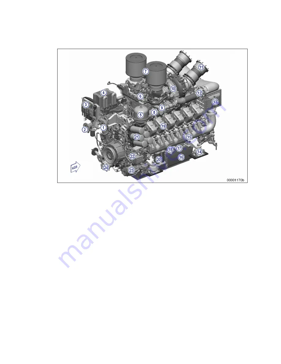
Engines with remote heat exchanger and vertical air intake

1 Coolant outlet to remote

cooling system

2 Coolant inlet from remote

cooling system

3 Engine management and

monitoring

4 Oil cooler
5 Centrifugal oil filter
6 Crankcase breather
7 Dry-type air filter
8 Exhaust manifold
9 Recirculation line

10 Exhaust turbocharger
11 Exhaust outlet
12 Air pipe to intercooler
13 Intercooler
14 Engine mounts
15 Charge-air line
16 Oil pan
17 Oil filler neck
18 Crankcase

19 Cylinder head
20 Fuel filter
21 Oil filter
22 HP fuel pump
23 Battery-charging generator
24 Bilge pump (option)

KGS Free end

Overview drawing is also valid for 16V engines.

30 | Product Summary | MS150068/01E 2014-01

TIM-ID: 0000009990 - 007

Summary of Contents for 12 V 4000 M23F

Page 1: ...Operating Instructions Diesel engine 12 V 4000 M23F 12 V 4000 M23S 16 V 4000 M23F 16 V 4000 M23S MS150068 01E ...

Page 2: ...tten permission of MTU Friedrichshafen GmbH This restriction also applies to copyright distribution translation mi crofilming and storage or processing on electronic systems including data bases and online services This handbook is provided for use by maintenance and operating personnel in order to avoid malfunctions or damage during operation Subject to alterations and amendments ...

Page 3: ...Commissioning Note ...

Page 4: ......

Page 5: ... out of service periods 3 weeks 79 3 7 Checks prior to start up 80 3 8 Fuel treatment system Putting into operation 81 3 9 Fuel treatment system Switching on 84 3 10 Fuel treatment system Shutdown 85 3 11 Stopping the engine 86 3 12 Emergency engine stop 87 3 13 After stopping the engine 88 3 14 Plant Cleaning 89 4 Maintenance 4 1 Maintenance task reference table QL1 90 5 Troubleshooting 5 1 Troub...

Page 6: ...ef bore check 241 6 15 7 Engine coolant Sample extraction and analysis 242 6 15 8 Engine coolant filter Replacement 243 6 15 9 Preheating unit 244 6 15 10 Preheater Overhaul 247 6 15 11 Preheater Function and leak tightness check 248 6 16 Raw Water Pump with Connections 249 6 16 1 Raw water pump Relief bore check 249 6 17 Engine Mounting Support 250 6 17 1 Engine mounting Check 250 6 18 Battery Ch...

Page 7: ...onfiguration approved by the manufacturer in writ ing including engine control parameters In compliance with all safety regulations and in adherence with all warning notices in this manual In accordance with the maintenance requirements over the entire service life of the product Main tenance Schedule In compliance with the maintenance and repair instructions contained in this manual in particular...

Page 8: ...ork on or around the product This personnel must be instructed repeatedly Personnel requirements All work on the product shall be carried out by trained and qualified personnel only Training at the Training Center of the manufacturer Qualified personnel specialized in mechanical and plant engineering The operator must define the responsibilities of the personnel involved in operation maintenance r...

Page 9: ...rt pallet or transport with equipment for heavy loads forklift truck Prior to transporting the engine it is imperative to install transportation locking devices for crankshaft and engine mounts Secure the engine against tilting during transportation The engine must be especially secured against slipping or tilting when going up or down inclines and ramps Setting the engine down after transport Pla...

Page 10: ...nce work Do not blow out the interior of the flywheel housing or the starter with compressed air Clean the flywheel housing inside with a class H dust extraction device Observe the safety data sheet Safety regulations during maintenance and repair work Take special care when removing ventilation or plug screws from the product Cover the screw or plug with a rag to prevent fluids escaping under pre...

Page 11: ... pipes which are to be welded from the product beforehand Hydraulic installation and removal Check satisfactory function and safe operating condition of tools jigs and fixtures to be used Use only the specified jigs and fixtures for hydraulic removal installation procedures Observe the max permissible force on pressure specified for the jig fixture Do not attempt to bend or apply force to lines Be...

Page 12: ...y stop feature Store spare parts properly prior to replacement i e protect them against moisture in particular Pack defective electronic components and assemblies in a suitable manner when dispatched for repair i e protected in particular against moisture and impact and wrapped in anti static foil if necessary Working with laser equipment When working with laser equipment always wear special laser...

Page 13: ... are prohibited by emission regulations Emission control units systems may only be maintained exchanged or repaired if the components used for this purpose are approved by the manu facturer Noncompliance with these guidelines will invalidate the design type approval issued by the emissions regulation authorities The manufacturer does not accept any liability for violations of the emission regulati...

Page 14: ...o be replaced Carry out leak test in accordance with the specifications Paints and varnishes Observe the relevant safety data sheet for all materials When painting in areas other than spray booths equipped with extractors ensure good ventilation Make sure that neighboring work areas are not adversely affected There must be no naked flames in the vicinity No smoking Observe fire prevention regulati...

Page 15: ... event of a situation involving potential danger Consequences Minor or moderate injuries Remedial action NOTICE In the event of a situation involving potentially adverse effects on the product Consequences Material damage Remedial action Additional product information Safety notices u This manual with all safety instructions and safety notices must be issued to all personnel involved in operation ...

Page 16: ...unt of heat to be dissipated by the coolant absolute gas tightness Turbocharging Sequential turbocharging with internal engine coolant controlled charge air cooling The right hand ex haust turbocharger is cut in and cut out on 12V and 16V engines with electronically controlled hydraul ically actuated flaps Cooling system Split circuit engine cooling system with remote or engine mounted heat exchan...

Page 17: ... charging generator Open bus interface to the plant SAE J1939 Emergency stop function with line break monitoring Redundant supply voltage input Emergency air shutoff flap control option Key switch logic Interface to ECU and EMU MCS5 dialog interface Control of an MTU lube oil priming pump power components in separate MTU PPC Box Connection facility for an MTU Local Operating Station LOS Serial RS4...

Page 18: ...U marine engine Series 4000M53R to M93L may be operated in low load operation State of the art design and equipment features e g TE coolant circuit sequential turbocharging jacketed coolant cooled exhaust lines Common Rail fuel injection and cylinder cutout allow engine operation at low load Nevertheless low load operation at engine load below 15 of the nominal rating is permitted for max 100 hour...

Page 19: ... of rated power takes place in single ETC mode with only one exhaust turbocharger running To ensure the functionality of the control mechanism and of the exhaust flap of the turbocharger which does not run in low load operation it is recommended to operate the engine with both exhaust turbochargers running after 100 operating hours in low load oper ation at the latest SOLAS Fire protection specifi...

Page 20: ...e after LP pump 1 SOLAS clip on the fuel line on fuel filter head retainer 1 SOLAS clip on the fuel line on HP pump 2 SOLAS clip on the fuel line after fuel filter head 20 Product Summary MS150068 01E 2014 01 TIM ID 0000010054 009 ...

Page 21: ...OLAS clips on the fuel line on fuel filter head Lube oil system oil lines with oil pressure 1 8 bar All lines with SOLAS compliant covers for pipe connections according to MTU standard MTN5233 are shown MS150068 01E 2014 01 Product Summary 21 TIM ID 0000010054 009 ...

Page 22: ...cylinder ETC B1 1 SOLAS clips on air flap switching cylinder ETC B1 2 SOLAS clips on flap control T adapt er ETC B1 1 SOLAS clips on distributor element 2 SOLAS clips on oil return 22 Product Summary MS150068 01E 2014 01 TIM ID 0000010054 009 ...

Page 23: ...l line to ETC 2 SOLAS clip on oil line to flap control 3 SOLAS clip on oil line to recircula tion valve 4 SOLAS clips on oil line from main gallery 1 SOLAS clips on recirculation valve MS150068 01E 2014 01 Product Summary 23 TIM ID 0000010054 009 ...

Page 24: ... on HP pump oil supply on HP pump 1 SOLAS clip on HP pump oil supply on equipment carrier 1 SOLAS clip on ETC oil supply 2 SOLAS clip on ETC oil supply 24 Product Summary MS150068 01E 2014 01 TIM ID 0000010054 009 ...

Page 25: ...r on oil filter cartridge Special connections The following types of union are spray proof in case of leakage even without covers and have been con firmed as being SOLAS compliant by GL and DNV MS150068 01E 2014 01 Product Summary 25 TIM ID 0000010054 009 ...

Page 26: ...thread The pressure is so greatly reduced by this and the faulty sealing ring 1 that any leakage is not under pressure Plug in pipe union b The sleeve 3 covers the joint to prevent lateral spray Only leak off along the line is possible the pressure is decreases significantly if an O ring 2 defect occurs The union is confirmed as being SOLAS compliant by DNV and GL 26 Product Summary MS150068 01E 2...

Page 27: ...all type seal area 20 Leak fuel connection The HP fuel line is sealed by the thrust ring 8 If leakage in the area of the thrust ring 8 or the HP line 2 occurs the emerging fuel is routed to the leakage chamber The leaking fuel is drained off without pressure via the leakage overflow bore 7 The leakage chamber is sealed toward the outside by the O rings 3 This prevents leakage egress The union is c...

Page 28: ...t 8 Air pipe to intercooler 9 Intercooler 10 Recirculation line 11 Exhaust manifold 12 Engine mounts 13 Charge air line 14 Oil pan 15 Oil filler neck 16 Crankcase 17 Cylinder head 18 Fuel filter 19 Battery charging generator 20 HP fuel pump 21 Oil filter 22 Bilge pump option 23 Coolant outlet to remote cooling system 24 Coolant inlet from remote cooling system KGS Free end 28 Product Summary MS150...

Page 29: ...r 8 Dry type air filter 9 Exhaust turbocharger 10 Exhaust outlet 11 Air pipe to intercooler 12 Recirculation line 13 Exhaust manifold 14 Intercooler 15 Charge air line 16 Engine mounts 17 Oil pan 18 Oil filler neck 19 Cylinder head 20 Crankcase 21 Fuel filter 22 Battery charging generator 23 HP fuel pump 24 Oil filter 25 Bilge pump option 26 Raw water inlet KGS Free end MS150068 01E 2014 01 Produc...

Page 30: ... air filter 8 Exhaust manifold 9 Recirculation line 10 Exhaust turbocharger 11 Exhaust outlet 12 Air pipe to intercooler 13 Intercooler 14 Engine mounts 15 Charge air line 16 Oil pan 17 Oil filler neck 18 Crankcase 19 Cylinder head 20 Fuel filter 21 Oil filter 22 HP fuel pump 23 Battery charging generator 24 Bilge pump option KGS Free end Overview drawing is also valid for 16V engines 30 Product S...

Page 31: ...ine mounts 17 Oil pan 18 Oil filler neck 19 Crankcase 20 Cylinder head 21 Fuel filter 22 Oil filter 23 HP fuel pump 24 Battery charging generator 25 Bilge pump option 26 Raw water inlet KGS Free end Overview drawing is also valid for 16V engines Engine model designation Key to the engine model designations 12 16V 4000 Mxy z 12 16 Number of cylinders V Cylinder arrangement V engine 4000 Series M Ap...

Page 32: ...2V 4000 M with external cooling 1 B49 charge air temp air recirculation valve Y26 air recirculation valve A 2 B4 A1 B4 B6 single ex haust temp A1 A6 B1 B6 3 B33 fuel temperature in common rail 32 Product Summary MS150068 01E 2014 01 TIM ID 0000038758 002 ...

Page 33: ...of filter 3 B5 1 oil pressure down stream of filter 4 B33 fuel temperature in common rail 5 B48 fuel pressure in com mon rail 6 B1 camshaft speed 7 B54 oil refill pump pres sure 8 B6 2 coolant tempera ture 9 B6 coolant temperature MS150068 01E 2014 01 Product Summary 33 TIM ID 0000038758 002 ...

Page 34: ... cooling 1 B4 21 exhaust tempera ture A bank 2 B4 22 exhaust tempera ture B bank 3 B13 crankshaft speed 4 S37 2 safety switch 5 S37 1 safety switch 6 B13 2 crankshaft speed 34 Product Summary MS150068 01E 2014 01 TIM ID 0000038758 002 ...

Page 35: ...air temperature 3 B44 1 turbocharger A speed 4 B10 charge air pressure 5 B34 3 fuel pressure up stream of filter 6 B34 2 fuel pressure up stream of filter 7 B34 1 fuel pressure down stream of filter 8 F46 fuel overflow level MS150068 01E 2014 01 Product Summary 35 TIM ID 0000038758 002 ...

Page 36: ...of engine 12V 4000 M external cooling 1 B44 2 turbocharger B speed 2 Y27 turbocharger control valve 3 B16 coolant pressure 4 B9 charge air tempera ture 36 Product Summary MS150068 01E 2014 01 TIM ID 0000038758 002 ...

Page 37: ...op view 12V 4000 M integral cooling 1 B4 A1 B4 B6 single ex haust temp A1 A6 B1 B6 2 B33 fuel temperature in common rail 3 F33 coolant level MS150068 01E 2014 01 Product Summary 37 TIM ID 0000038758 002 ...

Page 38: ...of filter 3 B5 1 oil pressure down stream of filter 4 B33 fuel temperature in common rail 5 B48 fuel pressure in com mon rail 6 B1 camshaft speed 7 B54 oil refill pump pres sure 8 B6 2 coolant tempera ture 9 B6 coolant temperature 38 Product Summary MS150068 01E 2014 01 TIM ID 0000038758 002 ...

Page 39: ... cooling 1 B4 21 exhaust tempera ture A bank 2 B4 22 exhaust tempera ture B bank 3 B13 crankshaft speed 4 S37 2 safety switch 5 S37 1 safety switch 6 B13 2 crankshaft speed MS150068 01E 2014 01 Product Summary 39 TIM ID 0000038758 002 ...

Page 40: ...air recirculation valve A 3 B3 intake air temperature 4 B44 1 turbocharger A speed 5 B10 charge air pressure 6 B34 3 fuel pressure up stream of filter 7 B34 2 fuel pressure up stream of filter 8 B34 1 fuel pressure down stream of filter 9 F46 fuel overflow level 40 Product Summary MS150068 01E 2014 01 TIM ID 0000038758 002 ...

Page 41: ... 4000 M integral cooling 1 B44 2 turbocharger B speed 2 Y27 turbocharger control valve 3 B16 coolant pressure 4 B21 raw water pressure 5 B9 charge air tempera ture MS150068 01E 2014 01 Product Summary 41 TIM ID 0000038758 002 ...

Page 42: ...nal cooling 1 B49 charge air temp air recirculation valve Y26 air recirculation valve A 2 B4 A1 B4 B8 single ex haust temp A1 A8 B1 B8 3 B33 fuel temperature in common rail 42 Product Summary MS150068 01E 2014 01 TIM ID 0000038758 002 ...

Page 43: ...of filter 3 B5 1 oil pressure down stream of filter 4 B33 fuel temperature in common rail 5 B48 fuel pressure in com mon rail 6 B1 camshaft speed 7 B54 oil refill pump pres sure 8 B6 2 coolant tempera ture 9 B6 coolant temperature MS150068 01E 2014 01 Product Summary 43 TIM ID 0000038758 002 ...

Page 44: ... cooling 1 B4 21 exhaust tempera ture A bank 2 B4 22 exhaust tempera ture B bank 3 B13 crankshaft speed 4 S37 2 safety switch 5 S37 1 safety switch 6 B13 2 crankshaft speed 44 Product Summary MS150068 01E 2014 01 TIM ID 0000038758 002 ...

Page 45: ...air temperature 3 B44 1 turbocharger A speed 4 B10 charge air pressure 5 B34 3 fuel pressure up stream of filter 6 B34 2 fuel pressure up stream of filter 7 B34 1 fuel pressure down stream of filter 8 F46 fuel overflow level MS150068 01E 2014 01 Product Summary 45 TIM ID 0000038758 002 ...

Page 46: ...of engine 16V 4000 M external cooling 1 B44 2 turbocharger B speed 2 Y27 turbocharger control valve 3 B16 coolant pressure 4 B9 charge air tempera ture 46 Product Summary MS150068 01E 2014 01 TIM ID 0000038758 002 ...

Page 47: ...op view 16V 4000 M integral cooling 1 B4 A1 B4 B8 single ex haust temp A1 A8 B1 B8 2 B33 fuel temperature in common rail 3 F33 coolant level MS150068 01E 2014 01 Product Summary 47 TIM ID 0000038758 002 ...

Page 48: ...of filter 3 B5 1 oil pressure down stream of filter 4 B33 fuel temperature in common rail 5 B48 fuel pressure in com mon rail 6 B1 camshaft speed 7 B54 oil refill pump pres sure 8 B6 2 coolant tempera ture 9 B6 coolant temperature 48 Product Summary MS150068 01E 2014 01 TIM ID 0000038758 002 ...

Page 49: ... cooling 1 B4 21 exhaust tempera ture A bank 2 B4 22 exhaust tempera ture B bank 3 B13 crankshaft speed 4 S37 2 safety switch 5 S37 1 safety switch 6 B13 2 crankshaft speed MS150068 01E 2014 01 Product Summary 49 TIM ID 0000038758 002 ...

Page 50: ...air recirculation valve A 3 B3 intake air temperature 4 B44 1 turbocharger A speed 5 B10 charge air pressure 6 B34 3 fuel pressure up stream of filter 7 B34 2 fuel pressure up stream of filter 8 B34 1 fuel pressure down stream of filter 9 F46 fuel overflow level 50 Product Summary MS150068 01E 2014 01 TIM ID 0000038758 002 ...

Page 51: ... 4000 M integral cooling 1 B44 2 turbocharger B speed 2 Y27 turbocharger control valve 3 B16 coolant pressure 4 B21 raw water pressure 5 B9 charge air tempera ture MS150068 01E 2014 01 Product Summary 51 TIM ID 0000038758 002 ...

Page 52: ...r to the cylinders on the left hand side of the engine and the letter B 3 to refer to the cylinders on the right hand side The cylinders of each bank are numbered consecutively starting with No 1 at the driving end The numbering of other engine components also starts with no 1 at the driving end 1 Left hand side of engine 2 Free end 3 Right hand side of engine 4 Driving end 52 Product Summary MS15...

Page 53: ...eight C 16V 4000 M23S 23F 33S 33F 43S 16V 4000 M53R 53 63R 63 63L approx 3108 mm approx 1690 mm approx 1850 mm approx 2064 mm With engine mounted heat exchanger Engine model Length A Width B without silencer Width B with si lencer Height C 16V 4000 M23S 23F 33S 33F 43S approx 3388 mm approx 1690 mm approx 1850 mm approx 2064 mm MS150068 01E 2014 01 Product Summary 53 TIM ID 0000010043 004 ...

Page 54: ...mm approx 2448 mm 16V 4000 M23S 23F 33S 33F 43S 16V 4000 M53R 53 63R 63 63L approx 3108 mm approx 1602 mm approx 2361 mm approx 2441 mm With engine mounted heat exchanger Engine model Length A Width B Height C without silencer Height C with si lencer 12V 4000 M23S 23F 33S 33F 12V 4000 M53R 53 63 approx 2857 mm approx 1602 mm approx 2368 mm approx 2448 mm 16V 4000 M23S 23F 33S 33F 43S 16V 4000 M53R...

Page 55: ...ng Sequence 2 4 1 Firing order Cylinders Firing order 12 V A1 B5 A5 B3 A3 B6 A6 B2 A2 B4 A4 B1 16 V A1 A7 B4 B6 A4 B8 A2 A8 B3 B5 A3 A5 B2 A6 B1 B7 MS150068 01E 2014 01 Product Summary 55 TIM ID 0000023263 002 ...

Page 56: ...bove sea level m 100 100 100 100 POWER DATA power ratings are net brake power as per ISO 3046 Heat exchanger mounted Heat exchanger separate Rated engine speed A rpm 1500 1500 1500 1500 Continuous power ISO 3046 10 over load capability design power DIN 6280 ISO 8528 A kW 1140 1140 1140 1140 GENERAL CONDITIONS for maximum power Heat exchanger mounted Heat exchanger separate Intake depression new fi...

Page 57: ...operating pressure before engine from R bar 5 0 5 0 5 0 5 0 Lube oil operating pressure before engine to R bar 6 0 6 0 6 0 6 0 Lube oil operating pressure low idle meas point before engine R bar FUEL SYSTEM Heat exchanger mounted Heat exchanger separate Fuel pressure at supply connection to en gine min when engine is starting L bar 0 1 0 1 0 1 0 1 Fuel pressure at supply connection to en gine min ...

Page 58: ...s N N N N Oil change quantity max standard oil system option max operating inclina tions R Liters 265 265 265 265 Oil pan capacity at dipstick mark min standard oil system option max oper ating inclinations L Liters 195 195 195 195 Oil pan capacity at dipstick mark max standard oil system option max oper ating inclinations L Liters 235 235 235 235 WEIGHTS MAIN DIMENSIONS Heat exchanger mounted Hea...

Page 59: ...gs are net brake power as per ISO 3046 Heat exchanger mounted Heat exchanger separate Rated engine speed A rpm 1800 1800 1800 1800 Continuous power ISO 3046 10 over load capability design power DIN 6280 ISO 8528 A kW 1380 1380 1380 1380 GENERAL CONDITIONS for maximum power Heat exchanger mounted Heat exchanger separate Intake depression new filter A mbar 15 15 15 15 Intake depression max L mbar 30...

Page 60: ... oil operating pressure low idle meas point before engine R bar FUEL SYSTEM Heat exchanger mounted Heat exchanger separate Fuel pressure at supply connection to en gine min when engine is starting L bar 0 1 0 1 0 1 0 1 Fuel pressure at supply connection to en gine min when engine is running L bar 0 3 0 3 0 3 0 3 Fuel pressure at supply connection to en gine max when engine is starting L bar 1 5 1 ...

Page 61: ...x operating inclina tions R Liters 265 265 265 265 Oil pan capacity at dipstick mark min standard oil system option max operat ing inclinations L Liters 195 195 195 195 Oil pan capacity at dipstick mark max standard oil system option max operat ing inclinations L Liters 235 235 235 235 WEIGHTS MAIN DIMENSIONS Heat exchanger mounted Heat exchanger separate Engine dry weight with attached standard a...

Page 62: ...re net brake power as per ISO 3046 Heat exchanger mounted Heat exchanger separate Rated engine speed A rpm 1800 1800 1800 1800 Continuous power ISO 3046 10 over load capability design power DIN 6280 ISO 8528 A kW 1380 1380 1380 1380 GENERAL CONDITIONS for maximum power Heat exchanger mounted Heat exchanger separate Intake depression new filter A mbar 15 15 15 15 Intake depression max L mbar 30 30 ...

Page 63: ... oil operating pressure low idle meas point before engine R bar FUEL SYSTEM Heat exchanger mounted Heat exchanger separate Fuel pressure at supply connection to en gine min when engine is starting L bar 0 1 0 1 0 1 0 1 Fuel pressure at supply connection to en gine min when engine is running L bar 0 3 0 3 0 3 0 3 Fuel pressure at supply connection to en gine max when engine is starting L bar 1 5 1 ...

Page 64: ...x operating inclina tions R Liters 265 265 265 265 Oil pan capacity at dipstick mark min standard oil system option max operat ing inclinations L Liters 195 195 195 195 Oil pan capacity at dipstick mark max standard oil system option max operat ing inclinations L Liters 235 235 235 235 WEIGHTS MAIN DIMENSIONS Heat exchanger mounted Heat exchanger separate Engine dry weight with attached standard a...

Page 65: ...gs are net brake power as per ISO 3046 Heat exchanger mounted Heat exchanger separate Rated engine speed A rpm 1500 1500 1500 1500 Continuous power ISO 3046 10 over load capability design power DIN 6280 ISO 8528 A kW 1520 1520 1520 1520 GENERAL CONDITIONS for maximum power Heat exchanger mounted Heat exchanger separate Intake depression new filter A mbar 15 15 15 15 Intake depression max L mbar 30...

Page 66: ...be oil operating pressure low idle meas point before engine R bar FUEL SYSTEM Heat exchanger mounted Heat exchanger separate Fuel pressure at supply connection to en gine min when engine is starting L bar 0 1 0 1 0 1 0 1 Fuel pressure at supply connection to en gine min when engine is running L bar 0 3 0 3 0 3 0 3 Fuel pressure at supply connection to en gine max when engine is starting L bar 1 5 ...

Page 67: ...operating inclina tions R Liters 280 280 280 280 Oil pan capacity at dipstick mark min standard oil system option max operat ing inclinations L Liters 210 210 210 210 Oil pan capacity at dipstick mark max standard oil system option max operat ing inclinations L Liters 250 250 250 250 WEIGHTS MAIN DIMENSIONS Heat exchanger mounted Heat exchanger separate Engine dry weight with attached standard acc...

Page 68: ...gs are net brake power as per ISO 3046 Heat exchanger mounted Heat exchanger separate Rated engine speed A rpm 1800 1800 1800 1800 Continuous power ISO 3046 10 over load capability design power DIN 6280 ISO 8528 A kW 1840 1840 1840 1840 GENERAL CONDITIONS for maximum power Heat exchanger mounted Heat exchanger separate Intake depression new filter A mbar 15 15 15 15 Intake depression max L mbar 30...

Page 69: ...be oil operating pressure low idle meas point before engine R bar FUEL SYSTEM Heat exchanger mounted Heat exchanger separate Fuel pressure at supply connection to en gine min when engine is starting L bar 0 1 0 1 0 1 0 1 Fuel pressure at supply connection to en gine min when engine is running L bar 0 3 0 3 0 3 0 3 Fuel pressure at supply connection to en gine max when engine is starting L bar 1 5 ...

Page 70: ...operating inclina tions R Liters 280 280 280 280 Oil pan capacity at dipstick mark min standard oil system option max operat ing inclinations L Liters 210 210 210 210 Oil pan capacity at dipstick mark max standard oil system option max operat ing inclinations L Liters 250 250 250 250 WEIGHTS MAIN DIMENSIONS Heat exchanger mounted Heat exchanger separate Engine dry weight with attached standard acc...

Page 71: ...re net brake power as per ISO 3046 Heat exchanger mounted Heat exchanger separate Rated engine speed A rpm 1800 1800 1800 1800 Continuous power ISO 3046 10 over load capability design power DIN 6280 ISO 8528 A kW 1840 1840 1840 1840 GENERAL CONDITIONS for maximum power Heat exchanger mounted Heat exchanger separate Intake depression new filter A mbar 15 15 15 15 Intake depression max L mbar 30 30 ...

Page 72: ...be oil operating pressure low idle meas point before engine R bar FUEL SYSTEM Heat exchanger mounted Heat exchanger separate Fuel pressure at supply connection to en gine min when engine is starting L bar 0 1 0 1 0 1 0 1 Fuel pressure at supply connection to en gine min when engine is running L bar 0 3 0 3 0 3 0 3 Fuel pressure at supply connection to en gine max when engine is starting L bar 1 5 ...

Page 73: ...operating inclina tions R Liters 280 280 280 280 Oil pan capacity at dipstick mark min standard oil system option max operat ing inclinations L Liters 210 210 210 210 Oil pan capacity at dipstick mark max standard oil system option max operat ing inclinations L Liters 250 250 250 250 WEIGHTS MAIN DIMENSIONS Heat exchanger mounted Heat exchanger separate Engine dry weight with attached standard acc...

Page 74: ...3 Operation 3 1 Controls Automation system controls Refer to automation system operating instructions 74 Operation MS150068 01E 2014 01 TIM ID 0000016959 003 ...

Page 75: ...ith position of pressure indicator Page 190 HP fuel pump Only for engines without oil priming pump Fill HP fuel pump with new engine oil Page 177 Raw water pump if located above waterline only appli cable to engines with en gine mounted heat exchang er or with optional remote heat exchanger Prime with water approx 3 4 l Coolant circuit If engine is out of service for more than one year change engi...

Page 76: ...m Check coolant level Page 234 Coolant system Preheat coolant with preheating unit Fuel prefilter Drain Page 191 Check that suction side pressure indicated at the fuel prefilter pressure gauge is within the limit Page 190 Engine control system Refer to automation system operating instructions ECU Check plug connections Page 268 EIM Check plug connections Page 270 EMU Check plug connections Page 26...

Page 77: ...3 4 Starting the engine Start the engine via the automation system Refer to automation system operating instructions MS150068 01E 2014 01 Operation 77 TIM ID 0000017525 003 ...

Page 78: ...arge air cooler Check condensate drain Page 213 Air filter Check signal ring position of service indicator Page 216 Replace air filter Page 214 if the signal ring is completely visible in the service indicator control window HP fuel pump Check relief bores for fuel discharge Page 178 HT coolant pump Check relief bore for oil and coolant discharge and obstructions Page 241 Fuel prefilter optional C...

Page 79: ...eeks Tasks after extended out of service periods 3 weeks Note Operate fuel treatment system for at least 5 minutes 1 Start up fuel treatment system Page 81 2 Shut down fuel treatment system Page 85 MS150068 01E 2014 01 Operation 79 TIM ID 0000007730 005 ...

Page 80: ...lves 4 Switch on fuel treatment system Page 84 5 Check direction of rotation of pump 6 Vent bypass and fuel lines of the system a Open ball valve for pressure tank b Open ball valve for overflow tank c Close ball valve at the inlet to the fuel treatment system Result Bypass line is vented via the overflow tank d Open ball valve at the inlet to the fuel treatment system 7 Check the fuel treatment s...

Page 81: ...tic water drain 18 Water level electrode 19 Ball valve sample extrac tion inlet 20 Switchgear cabinet 21 Pump 22 Coarse filter 23 Fuel supply from tank 24 Tank Switching on fuel treatment system 1 Switch on fuel treatment system Page 84 2 Check differential pressure at differential pressure gage 8 Differential pressure in a new system 0 1 bar to 0 3 bar Result If no differential pressure is measur...

Page 82: ...e ball valve 5 at inlet to fuel treatment system Result The pressure upstream of the fuel treatment system increases until the overflow valve at the pump unit opens and fuel flows through bypass 3 and bypass 2 5 Open ball valve 19 Result Fuel emerges If no fuel emerges Open ball valve 5 at inlet to fuel treatment system No function of bypasses 2 and 3 carry out functional test of bypasses 2 and 3 ...

Page 83: ...ry pump draws fuel via bypass 2 directly from tank 24 5 Check suction pressure at the engine mounted fuel delivery pump Note If the suction pressure is within the permissible limits and engine operation is satisfactory 6 Operate engine at full load and monitor suction pressure Result If the suction pressure is within the specified limits simulation was successful MS150068 01E 2014 01 Operation 83 ...

Page 84: ...ore switching on ensure that all housings are closed Before switching on ensure that no work is in progress anywhere on the entire system Fuel treatment system Switching on 1 Carry out checks prior to start up Page 80 2 Switch on master switch on switchgear cabinet Result Signal lamp Control voltage present lights up 3 Switch on switch for pump Result Signal lamp Pump running lights up 84 Operatio...

Page 85: ...binet until water discharge from the outlet stops 2 Switch off fuel treatment system 3 Close ball valve at the inlet to the fuel treatment system 4 Close ball valve at the outlet of the fuel treatment system 5 Open drain valve until pressure has escaped from fuel treatment system MS150068 01E 2014 01 Operation 85 TIM ID 0000007732 005 ...

Page 86: ...3 11 Stopping the engine Stopping the engine via the automation system Refer to automation system operating instructions 86 Operation MS150068 01E 2014 01 TIM ID 0000017528 004 ...

Page 87: ...e stress to the engine plant Risk of overheating damage to components Initiate emergency stop only in emergency situations Emergency stop 1 Refer to automation system operating instructions 2 Follow instructions MS150068 01E 2014 01 Operation 87 TIM ID 0000017530 005 ...

Page 88: ...rature the antifreeze concentration is insufficient for the engine room tem perature antifreeze concentration is 50 and engine room temperature is below 40 C Raw water only on engines with engine mounted heat exchanger Drain if freezing temperatures are expected and the engine is to remain out of service for an extended period Engine control system Switch off Air intake and exhaust sys tem Out of ...

Page 89: ...pressed air gun directly at seals or electronic components such as connectors or ECUs Plant Cleaning 1 Carry out plant cleaning only in areas where an appropriate oil separator is provided environmental protection 2 Prior to putting the cleaning unit into operation read the Operating Instructions of the water steam jet unit carefully and observe the safety precautions 3 For external cleaning of th...

Page 90: ...1005 X Replace air filter Page 214 W1006 Replace fuel injectors Page 179 W1008 X Replace engine oil filter when changing engine oil or when the interval years is reached at the latest Page 223 W1009 Check layer thickness of the oil residue clean out and re place filter sleeve each time the oil is changed at the latest Page 227 W1011 Perform endoscopic examination Page 165 W1016 X Check condition o...

Page 91: ... W1675 X Replace fuel prefilter or fuel prefilter element Page 195 W1713 Injector Reset drift correction parameter CDC Page 266 Table 1 Maintenance task reference table QL1 MS150068 01E 2014 01 Maintenance 91 TIM ID 0000048360 001 ...

Page 92: ...art the system by actuating the key switch Running gear blocked engine cannot be barred manually u Contact Service Engine turns on starting but does not fire Cause Corrective action Poor rotation by starter Battery low or faulty u Charge or replace battery see separate documentation Engine cabling defective u Check Page 265 Engine governor defective u Contact Service Engine fires unevenly Cause Co...

Page 93: ...dicator Page 216 Intercooler dirty u Contact Service Exhaust turbocharger defective u Contact Service Coolant leaks at intercooler Cause Corrective action Intercooler leaky major coolant discharge u Contact Service Black exhaust gas Cause Corrective action Air supply Air filter clogged u Check signal ring position of service indicator Page 216 Fuel injection Injector faulty u Replace Page 179 Engi...

Page 94: ...ust gas Cause Corrective action Engine is not at operating temperature u Run engine to reach operating temperature Intercooler leaky u Contact Service 94 Troubleshooting MS150068 01E 2014 01 TIM ID 0000010520 004 ...

Page 95: ...th an overload protection If the maximum permissible current consumption is exceeded e g in case of a blockage or dry running the motor protection relay triggers and the pump is switched off u Reset motor protection relay Signal lamp Pre alarm is lit Cause Corrective action The differential pressure exceeded 1 3 bar u Replace coalescer filter element Page 257 Illuminated pushbutton Replace filter ...

Page 96: ...fault code 1 comprises 3 digits Fault messages may also be caused by faulty sensors actuators Contact Service to have sensors actuators tested and replaced as necessary if troubleshooting as described in the table Page 97 proves unsuccessful For explanations of alarm configuration parameters refer to PR 2 8008 100 Fault code list Page 97 96 Troubleshooting MS150068 01E 2014 01 TIM ID 0000016867 00...

Page 97: ...k may be exposed to heat u Contact Service 5 HI T Charge Air ZKP Number 2 0121 931 Charge air temperature too high limit value 1 Yellow alarm warning Cause Corrective action Charge air cooler not functioning correctly 1 Reduce power 2 Check charge air cooler 3 Contact Service 6 SS T Charge Air ZKP Number 2 0121 932 Charge air temperature too high limit value 2 Red alarm engine shutdown Cause Corre...

Page 98: ...ective action Coolant circuit for charge air defective 1 Check charge air cooler and coolant cooler 2 Contact Service 15 LO P Lube Oil ZKP Number 2 0100 921 Lube oil pressure too low limit value 1 Yellow alarm warning Cause Corrective action Insufficient oil 1 Check oil level top up as necessary Page 218 2 Contact Service 16 SS P Lube Oil ZKP Number 2 0100 922 Lube oil pressure too low limit value...

Page 99: ... 2 0127 931 Exhaust temperature too high B side limit value 1 Yellow alarm warning Cause Corrective action Wiring damage 1 Check air filter and wiring Page 265 2 Contact Service 22 SS T Exhaust B ZKP Number 2 0127 932 Exhaust temperature too high B side limit value 2 Red alarm engine shutdown Cause Corrective action Wiring damage 1 Check air filter and wiring Page 265 2 Contact Service 23 LO Coola...

Page 100: ...7 HI Level Leakage Fuel ZKP Number 2 0151 931 Leak off fuel level too high limit value 1 Yellow alarm warning Cause Corrective action Fuel lines leaking 1 Check fuel system 2 Contact Service 29 HI ETC Idle Speed Too High ZKP Number 1 8004 206 Yellow alarm warning Cause Corrective action Idling speed of one of the secondary turbochargers is too high u Contact Service 30 SS Engine Overspeed ZKP Numb...

Page 101: ...el filter differential oil pressure too high limit value 1 Yellow alarm warning Cause Corrective action Fuel filter not functioning correctly 1 Replace fuel filter Page 187 2 Contact Service 34 SS P Diff Fuel ZKP Number 2 0114 932 Fuel filter differential oil pressure too high limit value 2 Red alarm engine shutdown Cause Corrective action Fuel filter not functioning correctly 1 Replace fuel filte...

Page 102: ... 204 Yellow alarm warning Cause Corrective action ETC2 failed to cut in u Contact Service 44 LO Coolant Level Charge Air Cooler ZKP Number 2 0153 921 Coolant level of charge air cooler too low limit value 1 Yellow alarm warning Cause Corrective action Insufficient charge air coolant e g due to leaks in the charge air coolant circuit 1 Check coolant level Page 234 2 Contact Service 51 HI T Lube Oil...

Page 103: ...lant pressure too low limit value 2 Red alarm engine stop or reduced injection quantity Cause Corrective action Leak in coolant circuit 1 Check coolant level Page 234 2 Check coolant circuit 59 SS T Coolant L3 ZKP Number 2 0120 933 Coolant temperature too high low limit value 3 Red alarm forced idle Cause Corrective action Coolant circuit not functioning correctly e g damage leaks low coolant leve...

Page 104: ...tive action Crankcase exhaust system clogged or leaking 1 Reduce power 2 Replace oil mist fine separator element 3 Contact Service 64 SS P Crankcase ZKP Number 2 0106 932 Crankcase pressure too high limit value 2 Red alarm engine shutdown Cause Corrective action Crankcase exhaust system clogged or leaking 1 Reduce power 2 Replace oil mist fine separator element 3 Contact Service 65 LO P Fuel ZKP N...

Page 105: ...mage leaks low coolant level 1 Reduce power 2 Check coolant circuit 68 SS T Coolant ZKP Number 2 0120 932 Coolant temperature too high limit value 2 Red alarm engine shutdown Cause Corrective action Coolant circuit not functioning correctly e g damage leaks low coolant level u Check coolant circuit 81 AL Rail Leakage ZKP Number 1 8004 046 Leak Yellow alarm warning Cause Corrective action During st...

Page 106: ...Service 085 HI T Recirculation ZKP Number 2 0128 931 Recirculation temperature too high limit value 1 Cause Corrective action Charge air temperature before recirculation valve too high u Reduce power 086 SS T Recirculation ZKP Number 2 0128 932 Recirculation temperature too high limit value 2 Cause Corrective action Charge air temperature before recirculation valve too high u Reduce power 89 SS En...

Page 107: ...d Red alarm warning Cause Corrective action Starter rotates too slowly or does not rotate at all 1 Check for additional messages 2 Contact Service 93 SS T Preheat ZKP Number 2 1090 922 Preheating temperature too low limit value 2 Red alarm engine start interlock Cause Corrective action Preheating unit not functioning 1 Check preheater 2 Contact Service 94 LO T Preheat ZKP Number 2 1090 921 Preheat...

Page 108: ...ng system faulty Yellow alarm warning Cause Corrective action Hour meter faulty u Contact Service 118 LO ECU Power Supply Voltage ZKP Number 2 0140 921 Supply voltage too low limit value 1 Yellow alarm warning Cause Corrective action Supply voltage at engine governor too low 1 Check engine governor supply voltage 2 Contact Service 119 LOLO ECU Power Supply Voltage ZKP Number 2 0140 922 Supply volt...

Page 109: ...oltage 2 Contact Service 122 HI T ECU ZKP Number 2 0132 921 Electronics temperature too high limit value 1 Yellow alarm warning Cause Corrective action Electronics overheated 1 Reduce power 2 Improve engine room ventilation 141 AL Power too high ZKP Number 1 1088 007 Maximum value exceeded Yellow alarm warning Cause Corrective action Power mean value has exceeded the specified maximum value in the...

Page 110: ... engine governor indicated for each indiv module u Contact Service 180 AL CAN1 Node Lost ZKP Number 2 0500 680 Connection to a node on CAN bus 1 failed Yellow alarm warning Cause Corrective action Connection or communication with a node on CAN bus 1 has failed 1 Check devices connected to CAN 2 Check wiring Page 265 3 Contact Service 181 AL CAN2 Node Lost ZKP Number 2 0500 681 Connection to a node...

Page 111: ... governor 1 Check devices connected to CAN 2 Contact Service 184 AL CAN PU Data Flash Error ZKP Number 2 0500 684 CAN PU data flash error Cause Corrective action A program fault occurred while trying to copy a received PU data module into the flash module u Contact electronic Service 186 AL CAN1 Bus Off ZKP Number 2 0500 686 CAN controller 1 is in Bus Off status Yellow alarm automatic changeover t...

Page 112: ...d rate incompatibility 1 Check CAN bus for short circuit rectify short circuit as necessary 2 Check shielding improve shielding as necessary 3 Contact Service 189 AL CAN2 Error Passive ZKP Number 2 0500 689 CAN controller 2 error Yellow alarm warning Cause Corrective action Missing associated node minor disruptions or temporary bus overload 1 Check CAN bus for short circuit rectify short circuit a...

Page 113: ... is rectified when engine is restarted Page 77 3 Contact Service 203 SD T Charge Air ZKP Number 1 8004 571 Signal error charge air temperature sensor Yellow alarm warning Cause Corrective action Charge air temperature sensor faulty Short circuit or wire break 1 Check sensor and wiring B9 replace as necessary Page 265 2 Fault is rectified when engine is restarted Page 77 3 Contact Service 204 SD Le...

Page 114: ...sary Page 265 2 Fault is rectified when engine is restarted Page 77 3 Contact Service 207 SD T Exhaust B ZKP Number 1 8004 577 Signal error exhaust temperature sensor on B side Yellow alarm warning Cause Corrective action Exhaust temperature sensor on B side faulty Short circuit or wire break 1 Check sensor and wiring B4 22 replace as necessary Page 265 2 Fault is rectified when engine is restarte...

Page 115: ...gine is restarted Page 77 3 Contact Service 213 SD P Coolant Charge Air Cooler ZKP Number 1 8004 569 Charge air cooler coolant pressure sensor faulty Yellow alarm warning Cause Corrective action Charge air cooler coolant pressure sensor faulty Short circuit or wire break 1 Check sensor and wiring B43 replace as necessary Page 265 2 Fault is rectified when engine is restarted Page 77 3 Contact Serv...

Page 116: ...ace as necessary Page 265 2 Fault is rectified when engine is restarted Page 77 3 Contact Service 219 SD T Intake Air ZKP Number 1 8004 573 Signal error intake air temperature sensor Yellow alarm warning Cause Corrective action Intake air temperature sensor faulty Short circuit or wire break 1 Check sensor and cabling B3 replace as necessary Page 265 2 Fault is rectified when engine is restarted P...

Page 117: ...n engine is restarted Page 77 3 Contact Service 223 SD Level Coolant Charge Air Cooler ZKP Number 1 8004 583 Charge air cooler coolant level sensor faulty Yellow alarm warning Cause Corrective action Charge air cooler coolant level sensor faulty Short circuit or wire break 1 Check sensor and wiring F57 replace as necessary Page 265 2 Fault is rectified when engine is restarted Page 77 3 Contact Se...

Page 118: ...iring to connector B1 replace as necessary Page 265 2 Fault is rectified when engine is restarted Page 77 3 Contact Service 230 SD Crankshaft Speed ZKP Number 1 8004 498 Signal error crankshaft sensor Yellow alarm warning Cause Corrective action Crankshaft sensor faulty Short circuit or wire break 1 Check sensor and wiring B13 replace as necessary Page 265 2 Fault is rectified when engine is resta...

Page 119: ...k sensor and wiring B44 2 replace as necessary Page 265 2 Fault is rectified when engine is restarted Page 77 3 Contact Service 239 SD P Diff Fuel ZKP Number 1 8004 598 Differential pressure sensor for fuel faulty only occurs with SD alarm fuel before filter or fuel after filter Yellow alarm warning Cause Corrective action Fuel differential pressure sensor faulty u Check for additional messages 24...

Page 120: ...ensor faulty Short circuit or wire break u Check sensor and wiring replace as necessary Fault is rectified following engine restart 245 SD ECU Power Supply Voltage ZKP Number 2 8006 589 Signal error engine governor supply voltage Yellow alarm warning Cause Corrective action Internal ECU fault Electronics faulty 1 Replace Engine Control Unit 2 Contact Service 266 SD Speed Demand ZKP Number 2 8006 5...

Page 121: ...ge 77 3 Contact Service 270 SD Frequency Input ZKP Number 2 8006 590 Signal error frequency input Red alarm forced idle Cause Corrective action Frequency input faulty Short circuit or wire break 1 Check wiring Page 265 2 Check speed demand transmitter 3 Contact Service 301 AL Timing Cylinder A1 ZKP Number 1 8004 500 Time of flight measuring fault of injector Cause Corrective action Flight time val...

Page 122: ...h u Replace injector if the fault message appears frequently Page 179 306 AL Timing Cylinder A6 ZKP Number 1 8004 505 Time of flight measuring fault of injector Cause Corrective action Flight time value extremely low or extremely high u Replace injector if the fault message appears frequently Page 179 307 AL Timing Cylinder A7 ZKP Number 1 8004 506 Time of flight measuring fault of injector Cause ...

Page 123: ...h u Replace injector if the fault message appears frequently Page 179 312 AL Timing Cylinder B2 ZKP Number 1 8004 511 Time of flight measuring fault of injector Cause Corrective action Flight time value extremely low or extremely high u Replace injector if the fault message appears frequently Page 179 313 AL Timing Cylinder B3 ZKP Number 1 8004 512 Time of flight measuring fault of injector Cause ...

Page 124: ... u Replace injector if the fault message appears frequently Page 179 318 AL Timing Cylinder B8 ZKP Number 1 8004 517 Time of flight measuring fault of injector Cause Corrective action Flight time value extremely low or extremely high u Replace injector if the fault message appears frequently Page 179 319 AL Timing Cylinder B9 ZKP Number 1 8004 518 Time of flight measuring fault of injector Cause C...

Page 125: ...Fault is rectified when engine is restarted Page 77 3 Contact Service 323 AL Wiring Cylinder A3 ZKP Number 1 8004 522 Wiring fault cylinder A3 Yellow alarm misfire Cause Corrective action Short circuit fault in injector wiring cylinder A3 1 Check injector solenoid replace injector if necessary Page 179 2 Fault is rectified when engine is restarted Page 77 3 Contact Service 324 AL Wiring Cylinder A...

Page 126: ...Fault is rectified when engine is restarted Page 77 3 Contact Service 327 AL Wiring Cylinder A7 ZKP Number 1 8004 526 Wiring fault cylinder A7 Yellow alarm misfire Cause Corrective action Short circuit fault in injector wiring cylinder A7 1 Check injector solenoid replace injector if necessary Page 179 2 Fault is rectified when engine is restarted Page 77 3 Contact Service 328 AL Wiring Cylinder A...

Page 127: ... Fault is rectified when engine is restarted Page 77 3 Contact Service 331 AL Wiring Cylinder B1 ZKP Number 1 8004 530 Wiring fault cylinder B1 Yellow alarm misfire Cause Corrective action Short circuit fault in injector wiring cylinder B1 1 Check injector solenoid replace injector if necessary Page 179 2 Fault is rectified when engine is restarted Page 77 3 Contact Service 332 AL Wiring Cylinder ...

Page 128: ...Fault is rectified when engine is restarted Page 77 3 Contact Service 335 AL Wiring Cylinder B5 ZKP Number 1 8004 534 Wiring fault cylinder B5 Yellow alarm misfire Cause Corrective action Short circuit fault in injector wiring cylinder B5 1 Check injector solenoid replace injector if necessary Page 179 2 Fault is rectified when engine is restarted Page 77 3 Contact Service 336 AL Wiring Cylinder B...

Page 129: ...ult is rectified when engine is restarted Page 77 3 Contact Service 339 AL Wiring Cylinder B9 ZKP Number 1 8004 538 Wiring fault cylinder B9 Yellow alarm misfire Cause Corrective action Short circuit fault in injector wiring cylinder B9 1 Check injector solenoid replace injector if necessary Page 179 2 Fault is rectified when engine is restarted Page 77 3 Contact Service 340 AL Wiring Cylinder B10...

Page 130: ...Page 179 3 Fault rectified after each working cycle 4 Contact Service 343 AL Open Load Cylinder A3 ZKP Number 1 8004 542 Injector wiring fault cylinder A3 Yellow alarm misfire Cause Corrective action Disruption fault in injector wiring cylinder A3 1 Check injector wiring for open circuit 2 Exclude possible injector solenoid fault replace injector if necessary Page 179 3 Fault rectified after each ...

Page 131: ...Page 179 3 Fault rectified after each working cycle 4 Contact Service 347 AL Open Load Cylinder A7 ZKP Number 1 8004 546 Injector wiring fault cylinder A7 Yellow alarm misfire Cause Corrective action Disruption fault in injector wiring cylinder A7 1 Check injector wiring for open circuit 2 Exclude possible injector solenoid fault replace injector if necessary Page 179 3 Fault rectified after each ...

Page 132: ... Page 179 3 Fault rectified after each working cycle 4 Contact Service 351 AL Open Load Cylinder B1 ZKP Number 1 8004 550 Injector wiring fault cylinder B1 Yellow alarm misfire Cause Corrective action Disruption fault in injector wiring cylinder B1 1 Check injector wiring for open circuit 2 Exclude possible injector solenoid fault replace injector if necessary Page 179 3 Fault rectified after each...

Page 133: ...Page 179 3 Fault rectified after each working cycle 4 Contact Service 355 AL Open Load Cylinder B5 ZKP Number 1 8004 554 Injector wiring fault cylinder B5 Yellow alarm misfire Cause Corrective action Disruption fault in injector wiring cylinder B5 1 Check injector wiring for open circuit 2 Exclude possible injector solenoid fault replace injector if necessary Page 179 3 Fault rectified after each ...

Page 134: ...ge 179 3 Fault rectified after each working cycle 4 Contact Service 359 AL Open Load Cylinder B9 ZKP Number 1 8004 558 Injector wiring fault cylinder B9 Yellow alarm misfire Cause Corrective action Disruption fault in injector wiring cylinder B9 1 Check injector wiring for open circuit 2 Exclude possible injector solenoid fault replace injector if necessary Page 179 3 Fault rectified after each wo...

Page 135: ... shutdown possible Cause Corrective action Electronics faulty 1 Start ITS 2 Replace engine governor if required 3 Check additional messages if ITS indicates diagnosis Electronics OK e g wiring faulty 4 Check solenoid valve wiring 5 Contact Service 363 AL Stop Power Stage ZKP Number 1 8004 560 Internal electronic fault Red alarm engine shutdown Cause Corrective action Electronics faulty 1 Start ITS...

Page 136: ...ve action Short circuit or wire break on transistor output 1 TO 1 1 Check charger valve wiring repair as necessary 2 Replace engine governor 372 AL Wiring TO 2 ZKP Number 1 8004 635 Line disruption Cause Corrective action Short circuit or wire break on transistor output 2 TO 2 1 Check recirculation valve wiring repair as necessary 2 Replace engine governor 373 AL Wiring TO 3 ZKP Number 1 8004 636 ...

Page 137: ...break on transistor output plant side 2 TOP 2 u Check wiring to plant 383 AL Wiring TOP 3 ZKP Number 2 8006 640 Line disruption on digital input 3 Yellow alarm warning Cause Corrective action Short circuit or wire break on transistor output plant side 3 TOP 3 u Check wiring to plant 384 AL Wiring TOP 4 ZKP Number 2 8006 641 Line disruption on digital input 4 Yellow alarm warning Cause Corrective a...

Page 138: ... 2 Cause Corrective action Redundant coolant temperature reading too high engine stop 1 Check wiring and sensor 2 Contact Service 394 LO P Lube Oil Red ZKP Number 2 0112 921 Limit value 1 Cause Corrective action Redundant lube oil pressure reading too low 1 Check wiring and sensor 2 Contact Service 395 SS P Lube Oil Red ZKP Number 2 0112 922 Limit value 2 Cause Corrective action Redundant lube oil...

Page 139: ...alarm warning Cause Corrective action Wiring faulty No resistance over switch 1 Check wiring Page 265 2 Check target device input 3 Contact Service 402 AL Open Load Digital Input 3 ZKP Number 2 8006 627 Line disruption on digital input 3 Yellow alarm warning Cause Corrective action Wiring faulty No resistance over switch 1 Check wiring Page 265 2 Check target device input 3 Contact Service 403 AL ...

Page 140: ...1 Check wiring Page 265 2 Check target device input 3 Contact Service 406 AL Open Load Digital Input 7 ZKP Number 2 8006 631 Line disruption on digital input 7 Yellow alarm warning Cause Corrective action Wiring faulty No resistance over switch 1 Check wiring Page 265 2 Check target device input 3 Contact Service 407 AL Open Load Digital Input 8 ZKP Number 2 8006 632 Line disruption on digital inp...

Page 141: ...faulty current supply 1 Check wiring Page 265 2 Check supply 3 Contact Service 411 LOLO U PDU ZKP Number 2 0141 922 Injector voltage too low limit value 2 Red alarm engine shutdown Cause Corrective action Wiring damage or faulty current supply 1 Check wiring Page 265 2 Check supply 3 Acknowledge alarm 4 Contact Service 412 HI U PDU ZKP Number 2 0141 931 Injector voltage too high limit value 1 Yell...

Page 142: ...KP Number 2 0107 921 Coolant pressure in charge air cooler too low limit 1 Yellow alarm warning Cause Corrective action Leak in coolant circuit u Top up coolant 416 SS P Coolant Charge Air Cooler ZKP Number 2 0107 922 Coolant pressure in charge air cooler too low limit 2 Red alarm engine shutdown Cause Corrective action Leak in coolant circuit u Top up coolant 417 SD Level Water Fuel Prefilter ZKP...

Page 143: ...P Number 2 0160 922 Limit value 2 Cause Corrective action Input signal of Aux 1 has exceeded not attained limit value 2 depending on configuration u Determine cause of limit value violation and rectify fault 428 AL L1 T Aux 1 ZKP Number 2 0130 921 Limit value 1 Cause Corrective action Temperature signal of Aux 1 has exceeded not attained limit value 1 depending on configuration u Determine cause o...

Page 144: ...2 depending on configuration u Determine cause of limit value violation and rectify fault 444 SD U PDU ZKP Number 1 8004 578 Injector power stage supply voltage fault Yellow alarm warning Cause Corrective action Sensor defect of injector power stage or internal fault of engine governor u Replace Engine Control Unit 445 SD P Ambient Air ZKP Number 1 8004 580 Signal error ambient air pressure sensor...

Page 145: ... at turbine bypass flap u Contact Service 449 SS P Charge Air ZKP Number 2 0103 932 Charge air pressure too high limit value 2 Red alarm engine shutdown Cause Corrective action Fault at turbine bypass flap u Contact Service 450 SD Idle End Torque Input ZKP Number 2 8006 592 Signal error start end torque Yellow alarm warning Cause Corrective action Input signal for start end torque faulty Short cir...

Page 146: ...ause Corrective action Input signal of Aux 1 plant side has exceeded not attained limit value 1 depending on configuration u Determine cause of limit value violation and rectify fault 456 AL L2 Aux1 Plant ZKP Number 2 8006 651 Limit value 2 Cause Corrective action Input signal of Aux 1 plant side has exceeded not attained limit value 2 depending on configuration u Determine cause of limit value vi...

Page 147: ...1 pressure faulty short circuit or wire break u Check pressure transmitter and wiring replace as necessary Fault is rectified following engine restart 467 AL L2 T Aux 1 ZKP Number 2 0130 922 Limit value 2 Cause Corrective action Temperature signal of Aux 1 has exceeded not attained limit value 2 depending on configuration u Determine cause of limit value violation and rectify fault 468 SD T AUX 1 ...

Page 148: ... 77 3 Contact Service 471 SD Coil Current ZKP Number 1 8004 592 Signal error HP fuel control block Yellow alarm warning Cause Corrective action Actuation of HP fuel control block faulty Short circuit or wire break 1 Check sensor and wiring replace as necessary Page 265 2 Contact Service 472 AL Stop SD ZKP Number 2 8006 593 Engine stops Red alarm engine shutdown Cause Corrective action Engine stops...

Page 149: ...ct Service 476 AL Crash Rec Init Error ZKP Number 1 8010 007 Initialization error of crash recorder Cause Corrective action Initialization error of crash recorder u Contact Service 478 AL Comb Alarm Yel Plant ZKP Number 2 8006 001 Yellow combined alarm from system Yellow alarm warning Cause Corrective action Various causes possible u Check for additional messages 479 AL Comb Alarm Red Plant ZKP Nu...

Page 150: ...reak u Check sensor and wiring B4 23 replace as necessary 483 SD T Exhaust D ZKP Number 18 004 597 Cause Corrective action Exhaust temperature sensor on A side faulty Short circuit or wire break u Check sensor and wiring B4 24 replace as necessary 484 HI T Exhaust C ZKP Number 20 133 931 Limit value 1 Cause Corrective action Exhaust gas temperature C side too high 1 Reduce power 2 Contact Service ...

Page 151: ...llow alarm warning Cause Corrective action Clogged charge air circuit or fault in turbocharger u Reduce power 489 SS ETC3 Overspeed ZKP Number 2 3014 932 Speed of 2nd secondary turbocharger too high limit value 2 Red alarm engine shutdown Cause Corrective action Clogged charge air circuit or fault in turbocharger u Reduce power 490 HI ETC4 Overspeed ZKP Number 2 3015 931 Speed of the 3rd secondary...

Page 152: ...03 Yellow alarm warning Cause Corrective action ETC3 failed to cut in u Check control valve at turbocharger 3 500 AL Wiring POM Starter 1 ZKP Number 1 4500 900 Wiring fault connection of starter 1 at POM Yellow alarm warning Cause Corrective action Missing consumer Short circuit or wire break u Check connection between POM and starter 501 AL Wiring POM Starter 2 ZKP Number 1 4500 901 Wiring fault ...

Page 153: ...nerator and wiring Page 265 504 AL CAN POM Node Failure ZKP Number 1 4500 904 POM missing on CAN bus Yellow alarm warning Cause Corrective action If alarm 508 occurs in addition the resistor in the POM wiring is missing u Check connection and POM 506 AL Low Starter Voltage ZKP Number 1 4500 906 The battery voltage is too low for the starting process Yellow alarm warning Cause Corrective action Wir...

Page 154: ...ossible start cancelation Cause Corrective action Starter on POM could not be engaged 1 Repeat start 2 Check POM starter and wiring Page 265 3 Contact Service 519 Oil Level Calibration Error ZKP Number 1 0158 921 Error writing calibration value into flash or SD of level sensor Yellow alarm warning Cause Corrective action Oil level sensor or wiring faulty 1 Check sensor and wiring replace as necess...

Page 155: ...ted as backup medium for FDH u Contact Service configuration fault 544 AL Configuration Changed ZKP Number 2 0555 003 Yellow alarm Cause Corrective action This alarm is activated when the system configuration was changed e g because the ECU or SAM was exchanged u Contact Service configuration fault 549 AL Power Disruption ZKP Number 2 7001 952 Alarm from the emergency stop counter function Yellow ...

Page 156: ... valid enabling code is entered via the SAM display and key controls This enabling code can be requested via the Internet using a special procedure u Request activation code via Internet 576 AL ESCM Override ZKP Number 1 1075 083 Engine overload Yellow alarm warning Cause Corrective action Violation of corrected MCR or DBR MCR curve u Reduce power 577 SD T Lube Oil Pan ZKP Number 1 0137 900 Signal...

Page 157: ...p is too low limit value 1 Yellow alarm warning Cause Corrective action Oil level in oil refill tank too low 1 Check oil level top up as necessary Page 218 2 Contact Service 588 SD P Oil Refill Pump ZKP Number 1 0159 910 Signal error refill pump oil pressure sensor Yellow alarm warning Cause Corrective action Pressure sensor defective Short circuit or wire break 1 Check sensor and wiring replace a...

Page 158: ... sensor and wiring replace as necessary Page 265 2 Contact Service 601 SD ETC1 ETC2 ZKP Number 1 3011 227 Signal error ETC speed sensor 1 and 2 Yellow alarm warning Cause Corrective action ETC speed sensors 1 and 2 faulty Short circuit or wire break 1 Check sensor and wiring replace as necessary Page 265 2 Contact Service 602 AL CAN Engine Start Lock ZKP Number 2 1090 930 Start interlock from plan...

Page 159: ...pressure sensor before supplementary filter Yellow alarm warning Cause Corrective action Analog input signal for fuel pressure before supplementary filter faulty Short circuit or wire break 1 Check pressure transmitter and wiring replace as necessary Page 265 2 Fault is rectified when engine is restarted Page 77 3 Contact Service 641 AL System Restart by Watchdog ZKP Number 1 8012 902 System is re...

Page 160: ...e too high u 761 SD T Fuel b Engine ZKP Number 1 0080 900 Cause Corrective action Oil pan temperature sensor faulty Short circuit or wire break 1 Check sensor and wiring B24 replace as necessary Page 265 2 Contact Service 782 SD P Lube oil ETC A ZKP Number 1 0222 920 Cause Corrective action SD turbocharger lube oil pressure u 788 Cyl cutout detects turbocharger speed error ZKP Number 1 3000 069 Ca...

Page 161: ...alue 1 Cause Corrective action Lube oil pressure too low u Check ETC oil lubrication 867 AL L1 P Lube Oil ETC A ZKP Number 1 0222 923 Limit value 1 Cause Corrective action Lube oil pressure too low u Check ETC oil lubrication 868 AL L2 P Lube Oil ETC A ZKP Number 1 0222 924 Limit value 2 Cause Corrective action Lube oil pressure too low u Check ETC oil lubrication 869 AL L2 P Lube Oil ETC B ZKP Nu...

Page 162: ...ing engine parts Risk of crushing danger of parts of the body being caught or pulled in Before barring the engine make sure that there are no persons in the engine s danger zone After finishing work on the engine make sure that all safety devices are put back in place and all tools are removed from the engine Barring engine manually 1 Release screws 1 and remove end cov er 2 from flywheel housing ...

Page 163: ...No resistance other than compression re sistance must be encountered 4 Rotate crankshaft in engine direction of ro tation Result If the resistance exceeds the normal com pression resistance contact Service 5 Barring device is removed by same proce dure in reverse MS150068 01E 2014 01 Task Description 163 TIM ID 0000000917 010 ...

Page 164: ...6 1 2 Engine Barring with starting system Barring using the automation system Refer to automation system operating instructions 164 Task Description MS150068 01E 2014 01 TIM ID 0000017532 003 ...

Page 165: ...pattern First signs of marks left by lower cooling bores Running pattern seems darker No action required Darker areas of even or varying color intensity Beginning and end of the discoloration are not sharply defined and do not cover the entire stroke area Dark areas in the upper section of the cooling bore remaining cir cumference cannot be faulted Piston rings faultless Further endoscopic examina...

Page 166: ...Final steps 1 Install injector Page 180 2 Install cylinder head cover Page 176 166 Task Description MS150068 01E 2014 01 TIM ID 0000000015 016 ...

Page 167: ...und the liner It appears rather darker within the honed struc ture in contrast to the bright metallic running surface The honing pattern is undis turbed Discolorations extend in stroke direction and may be interrupted Findings not critical Corrosion fields spots Corrosion fields spots result from water condensed water with the valves in the overlap open position They are clearly visible due to the...

Page 168: ...ation are similar A thorough investigation and compliance with the above evaluation criteria allow an unambiguous evaluation To avoid unnecessary disassembly work it is recommended that another inspection be carried out after further operation of the engine 168 Task Description MS150068 01E 2014 01 TIM ID 0000000014 015 ...

Page 169: ... Overview For 12V engines 1 Vent pipe 2 Plug 3 Oil separator 4 Impactor carrier 5 Bracket 6 Oil line 7 Service block 8 Vent housing 9 Spigot pipe 10 Drain pipe 11 Bracket 12 Connection MS150068 01E 2014 01 Task Description 169 TIM ID 0000038424 001 ...

Page 170: ...ines 1 Vent pipe 2 Impactor carrier 3 Bracket 4 Oil line 5 Service block 6 Vent housing 7 Spigot pipe 8 Drain pipe 9 Bracket 10 Plug 11 Oil separator 170 Task Description MS150068 01E 2014 01 TIM ID 0000038424 001 ...

Page 171: ... Oil can contain combustion residues which are harmful to health Risk of injury and poisoning Wear protective clothing gloves and goggles safety mask Avoid contact with skin Do not inhale oil vapor Replacing oil mist fine separator 1 Remove screws 1 and take off together with holder 2 2 Replace oil mist fine separator 3 3 Replace O ring 4 if necessary 4 Replace further oil mist fine separators in ...

Page 172: ...are parts Designation Use Part No Qty Engine oil Valve gear Lubrication 1 Remove cylinder head covers Page 176 2 Fill oil chambers of valve bridges with oil 3 Fill oil chambers of rocker arms and adjust ing screws with oil 4 Install cylinder head covers Page 176 172 Task Description MS150068 01E 2014 01 TIM ID 0000000921 010 ...

Page 173: ...al Spare parts Designation Use Part No Qty Feeler gage Y20010128 1 Torque wrench 60 320 Nm F30452768 1 Socket wrench 24 mm F30039526 1 Engine oil Preparatory steps 1 Remove cylinder head cover Page 176 2 Install barring gear Page 162 3 The OT mark 1 on the flywheel if applica ble must not be used for reference MS150068 01E 2014 01 Task Description 173 TIM ID 0000012224 007 ...

Page 174: ... engines two crankshaft positions 1 Cylinder A1 is in firing TDC 2 Cylinder A1 is in overlap TDC I Inlet valve X Exhaust valve Diagram for 16V engines two crankshaft positions 1 Cylinder A1 is in firing TDC 2 Cylinder A1 is in overlap TDC I Inlet valve X Exhaust valve 174 Task Description MS150068 01E 2014 01 TIM ID 0000012224 007 ...

Page 175: ...e value exceeds 0 1 mm adjust valve clearance Adjusting valve clearance 1 Release locknut 1 2 Insert feeler gage 3 between valve bridge and rocker arm 3 Using Allen key set adjusting screw 2 so that the specified valve clearance is provid ed Note Feeler gage must just pass through the gap 4 Pull feeler gage 3 between valve bridge and rocker arm 5 Tighten locknut 1 to the specified tightening torqu...

Page 176: ...er head covers 1 prior to removal 2 Remove screws 3 4 with washers 2 5 3 Take off cylinder head cover 1 with O ring 6 from cylinder head 7 Installing cylinder head cover 1 Clean mounting surface 2 Check O ring 6 for damage replace as necessary 3 Coat O ring 6 with assembly compound 4 Position O ring 6 in groove of cylinder head cover 1 5 Fit cylinder head cover 1 on cylinder head 7 6 Install cylin...

Page 177: ...NG Oils oil vapors are combustible explosive Risk of fire and explosion Avoid open flames electric sparks and ignition sources Do not smoke NOTICE HP fuel pump not filled with engine oil Damage to components major material damage Ensure that th HP fuel pump is filled with engine oil before it is installed or put into operation Filling HP pump 1 Remove plug screw 1 2 Use pump oiler to fill HP pump ...

Page 178: ...ne s danger zone WARNING High level of engine noise when the engine is running Risk of damage to hearing Wear ear protectors HP pump Relief bore check 1 Visually inspect relief bore 1 for fuel dis charge 2 For jacketed HP lines leakage is indicated by the yellow combined alarm 3 If fuel discharge is found or indicated con tact Service 178 Task Description MS150068 01E 2014 01 TIM ID 0000012375 007...

Page 179: ...tor Replacement Special tools Material Spare parts Designation Use Part No Qty Injector Spare Parts Catalog Replacing injector u Remove injector and install new injector Page 180 MS150068 01E 2014 01 Task Description 179 TIM ID 0000000022 016 ...

Page 180: ...ch 60 320 Nm F30452768 1 Ratchet adapter F30027341 1 Assembly paste Optimoly Paste White T 40477 1 Assembly compound Kluthe Hakuform 30 11C Emulgier X00059351 1 Engine oil O ring Spare Parts Catalog WARNING Fuels are combustible Risk of fire and explosion Avoid open flames electrical sparks and ignition sources Do not smoke Preparatory steps 1 Shut off fuel supply to engine 2 Remove cylinder head ...

Page 181: ...Remove injector with installation removal jig 7 Remove installation removal jig 8 Remove sealing ring 4 from injector or use a self made hook to take it out of the cylinder head 9 Remove O rings 3 O ring 2 and damper ring 1 from injector 10 Clean all mating and sealing surfaces 11 Cover all connections and bores or seal with suitable plugs MS150068 01E 2014 01 Task Description 181 TIM ID 000000092...

Page 182: ...position of sealing ring 4 Fit new O rings 3 included in the scope of delivery of the injector O ring 2 and damping ring 1 onto the injector and coat with assembly compound Kluthe Hakuform 30 11C Emulgier 5 Remove oil carbon from sealing face on cyl inder head and protective sleeve with mill ing cutter 6 Insert injector into cylinder head ensuring that the HP line adapter is correctly aligned 7 Pr...

Page 183: ...Preload torque Engine oil 5 Nm to 10 Nm 13 Tighten screw 2 with torque wrench to the specified tightening torque Name Size Type Lubricant Value Standard Screw M12 Tightening torque 100 Nm 10 Nm 14 Tighten adapter 3 with torque wrench to the specified tightening torque Name Size Type Lubricant Value Standard Adapter Tightening torque 100 Nm 10 Nm Note Ensure special cleanness 15 Coat thread and sea...

Page 184: ...will void the emissions certification 18 Reset drift compensation CDC with Dia Sys E531920 If DiaSys is not available contact Service Final steps 1 Install cylinder head cover Page 176 2 Open fuel supply to engine 184 Task Description MS150068 01E 2014 01 TIM ID 0000000925 012 ...

Page 185: ...ementary fuel filter Overview 1 Storage tank 2 Day tank 3 Passive standard prefilter with water separator 4 LP pump 5 Supplementary fuel filter 6 Main engine filter MS150068 01E 2014 01 Task Description 185 TIM ID 0000012629 004 ...

Page 186: ...els are combustible Risk of fire and explosion Avoid open flames electrical sparks and ignition sources Do not smoke WARNING High level of engine noise when the engine is running Risk of damage to hearing Wear ear protectors NOTICE Damage to component Severe material damage For filter replacement with the engine running operate the engine at low engine load The filter which is to be replaced must ...

Page 187: ... engine is running Risk of damage to hearing Wear ear protectors NOTICE Damage to component Severe material damage For filter replacement with the engine running operate the engine at low engine load The filter which is to be replaced must be cut out for a brief period only Replacing fuel filter with the en gine stopped 1 Cut out the filter to be replaced 1 B Left filter cut out C Right filter cut...

Page 188: ...l filter 1 using an oil filter wrench 3 Clean sealing surface on filter head 4 Check sealing ring of new filter 1 and coat with fuel 5 Screw on filter 1 and tighten manually 6 Turn three way cock into position A where both filters are operational 7 Replace other fuel filters in the same way 188 Task Description MS150068 01E 2014 01 TIM ID 0000045359 001 ...

Page 189: ...ilters are operational 2 Open threaded vent plugs 1 3 Unlock fuel priming pump 2 screw out handle by turning it counterclockwise 4 Operate fuel priming pump 2 until bubble free fuel emerges from the threaded vent plugs 1 5 Close threaded vent plugs 1 6 Screw in handle by turning it clockwise 7 Verify that fuel priming pump 2 is locked Handle must be tightened 8 Put filters back into operation A Ri...

Page 190: ...if ferential pressure gauge 1 After installation of a new filter element align adjustable pointer 2 with pressure indicating pointer 3 of pressure gauge 1 2 Verify that differential pressure is within the limit Fuel prefilter Checking differential pressure 1 With the engine running at full load or rated power read off pressure at gauge 1 2 If differential pressure as indicated between position of ...

Page 191: ...ical sparks and ignition sources Do not smoke Draining fuel prefilter 1 Cut out the filter to be replaced A or B 1 Filter A cut out 2 Filter B cut out 2 Open vent plug 1 of filter to be drained 3 Open drain valve 2 4 Drain water and contaminants from filter until pure fuel emerges 5 Close drain cock 2 MS150068 01E 2014 01 Task Description 191 TIM ID 0000018510 004 ...

Page 192: ...el until fuel emerges from the vent pipe 3 8 Close vent valve 2 9 Open rotary slide valve 4 a little by ap prox 30 and open vent valve s 2 until fuel emerges from the vent pipe 3 10 Close vent valve s 2 11 Turn rotary slide valve 4 back to locked position 192 Task Description MS150068 01E 2014 01 TIM ID 0000018510 004 ...

Page 193: ... at low power Keep away from the engine s danger zone WARNING Fuels are combustible Risk of fire and explosion Avoid open flames electrical sparks and ignition sources Do not smoke WARNING High level of engine noise when the engine is running Risk of damage to hearing Wear ear protectors Flushing fuel prefilter 1 Cut out dirty filter 1 Filter A cut out 2 Filter B cut out MS150068 01E 2014 01 Task ...

Page 194: ...ing connection 1 on the suction side of the filter 3 Open vent valve 2 and fill with fuel until fuel emerges from the vent pipe 3 4 Close vent valve 2 5 Open rotary slide valve 4 a little by ap prox 30 and open vent valve s 2 until fuel emerges from the vent pipe 3 6 Close vent valve s 2 7 Turn rotary slide valve 4 back to locked position 8 Check differential pressure Page 190 Result Replace filte...

Page 195: ...g WARNING Tank is pressurized Risk of eye injuries resulting from fluid escaping under high pressure Open tank slowly Wear goggles or safety mask WARNING Fuels are combustible Risk of fire and explosion Avoid open flames electrical sparks and ignition sources Do not smoke WARNING Component is hot Risk of burning Wear protective gloves Fuel prefilter with water separa tor Filter element replacement...

Page 196: ...ing torque maximum half a turn per screw Name Size Type Lubricant Value Standard Screw Tightening torque 40 Nm 10 Connect filling pump to filling connection 1 on the suction side of the filter 11 Open vent valve 2 and fill with fuel until fuel emerges from the vent pipe 3 12 Close vent valve 2 13 Open rotary slide valve 4 a little by ap prox 30 and open vent valve s 2 until fuel emerges from the v...

Page 197: ...y mask WARNING Fuels are combustible Risk of fire and explosion Avoid open flames electrical sparks and ignition sources Do not smoke Fuel prefilter with water separa tor O ring replacement in rota ry slide valve 1 Open vent valves 1 carefully to make sure that the system is not pressurized 2 Open drain valves 6 and drain fuel 3 Remove rotary slide valve retainer 4 with handle 5 4 Remove rotary sl...

Page 198: ...rger 1 Impeller housing left 2 Impeller housing right 3 Washer 4 Nut 5 Shaft 6 Bearing bush 7 Shaft 8 Sprung pin 9 Sealing ring 10 Sealing flange 11 Bolt 12 Turbine housing right 13 Turbine housing left 198 Task Description MS150068 01E 2014 01 TIM ID 0000037654 001 ...

Page 199: ...sher 8 Bearing bush 9 Washer 10 Circlip 11 Circlip 12 Washer 13 Bearing bush 14 O ring 15 Bearing housing 16 Bolt 17 Nut 18 Dished washer 19 Dished washer 20 Dished washer 21 Stud bolt 22 Bolt 23 Washer 24 Blanking plate 25 Blanking plate 26 Washer 27 Bolt MS150068 01E 2014 01 Task Description 199 TIM ID 0000037654 001 ...

Page 200: ...n ring 9 Ring retainer 10 O ring 11 Retaining ring 12 Impeller 13 Magnetic nut 14 Grooved pin 15 Identification plate 16 Impeller housing 17 Plug bolt 18 Sealing ring 19 Sealing ring 20 Plug bolt 21 Clamping piece 22 Washer 23 Bolt 24 Bolt 25 Washer 200 Task Description MS150068 01E 2014 01 TIM ID 0000037654 001 ...

Page 201: ...asher 8 Bearing bush 9 Washer 10 Circlip 11 Circlip 12 Washer 13 Bearing bush 14 O ring 15 Bearing housing 16 Bolt 17 Nut 18 Dished washer 19 Dished washer 20 Dished washer 21 Stud bolt 22 Bolt 23 Washer 24 Bush 25 Pin 26 Wastegate 27 Bolt 28 Washer 29 Bush MS150068 01E 2014 01 Task Description 201 TIM ID 0000037654 001 ...

Page 202: ...8 Piston ring 9 Ring retainer 10 O ring 11 Retaining ring 12 Impeller 13 Magnetic nut 14 Bolt 15 Washer 16 Clamping piece 17 Impeller housing 18 Plug bolt 19 Sealing ring 20 Identification plate 21 Grooved pin 22 Plug bolt 23 Sealing ring 24 Bolt 25 Washer 202 Task Description MS150068 01E 2014 01 TIM ID 0000037654 001 ...

Page 203: ...Impeller housing 1 Impeller housing 2 Plug bolt 3 Sealing ring Bearing housing 1 Bearing housing 2 Sprung pin MS150068 01E 2014 01 Task Description 203 TIM ID 0000037654 001 ...

Page 204: ...Thrust bearing 1 Ball 2 Thrust bearing Magnetic nut 1 Magnetic nut 2 Magnet 204 Task Description MS150068 01E 2014 01 TIM ID 0000037654 001 ...

Page 205: ...the instructions of the cleaning agent manufacturer NOTICE Inappropriate cleaning tool Risk of damage to component Observe manufacturer s instructions Use appropriate cleaning tool NOTICE Incorrect installation of components and lines Damage to component Ensure that components lines are installed so that they are never under tension or strain Ensure correct installation position of components Prep...

Page 206: ...ler 5 Remove oil lines 2 6 Loosen clamp 1 7 Remove intake housing 3 with actuating cylinder 2 8 Remove coolant lines 1 from compressor housing 3 9 Remove coolant ventilation line 2 from compressor housing 3 206 Task Description MS150068 01E 2014 01 TIM ID 0000018629 006 ...

Page 207: ...sing with a smooth paint brush or brush 2 Clean compressor wheel 2 and bearing housing 1 3 Thoroughly remove cleaner from all compo nents 4 Fit new sealing rings between bearing housing compressor housing and plug in sleeves if necessary Final steps Horizontal air in take 1 Install compressor housing 2 MS150068 01E 2014 01 Task Description 207 TIM ID 0000018629 006 ...

Page 208: ...ue using a torque wrench Name Size Type Lubricant Value Standard Clamp Tightening torque 15 Nm 2 Nm 6 Install oil lines 2 Tighten threaded adapter at actuating cylinder to specified torque using a torque wrench Name Size Type Lubricant Value Standard Threaded adapter 10 G 1 4 A Tightening torque Engine oil 40 Nm 4 Nm 7 Install charge air pipework 1 between exhaust turbocharger and intercooler 8 In...

Page 209: ... filter Page 215 3 Seal all openings with suitable covers 4 Remove charge air pipework 1 from ex haust turbocharger to intercooler 5 Remove oil lines 2 6 Loosen clamp 1 7 Remove intake housing 3 with actuating cylinder 2 MS150068 01E 2014 01 Task Description 209 TIM ID 0000018629 006 ...

Page 210: ...te Do not use wire brushes scrapers or simi lar tools for cleaning 1 Clean compressor housing with a smooth paint brush or brush 2 Clean compressor wheel 2 and bearing housing 1 3 Thoroughly remove cleaner from all compo nents 4 Fit new sealing rings between bearing housing compressor housing and plug in sleeves if necessary 210 Task Description MS150068 01E 2014 01 TIM ID 0000018629 006 ...

Page 211: ...tening torque Engine oil 20 Nm 2 5 Nm 3 Install coolant ventilation line and coolant lines on compressor housing 4 Install intake housing 3 with actuating cyl inder 2 5 Align clamp 1 and tighten to specified torque using a torque wrench Name Size Type Lubricant Value Standard Clamp Tightening torque 15 Nm 2 Nm MS150068 01E 2014 01 Task Description 211 TIM ID 0000018629 006 ...

Page 212: ...ame Size Type Lubricant Value Standard Threaded adapter 10 G 1 4 A Tightening torque Engine oil 40 Nm 4 Nm 7 Install charge air pipework 1 between exhaust turbocharger and intercooler 8 Install air filter Page 215 9 Fill with engine coolant Page 239 212 Task Description MS150068 01E 2014 01 TIM ID 0000018629 006 ...

Page 213: ...t air jet at people Always wear safety goggles face mask and ear defenders Intercooler Checking conden sate drain for water discharge and obstruction 1 With the engine running check if air emerges from drain bore s on the left and right sides on engine driving end Result If no air emerges Clean condensate drain bore s Blow out with compressed air 2 If a large amount of coolant is continuously disc...

Page 214: ...are parts Designation Use Part No Qty Air filter Spare Parts Catalog Replacing the air filter 1 Remove old air filter and install new air filter Page 215 2 Reset signal ring of contamination indicator Page 216 214 Task Description MS150068 01E 2014 01 TIM ID 0000005447 009 ...

Page 215: ...s in the flange of the intake housing 3 and clean it 4 Attach air filter 1 with clamp 2 onto in take housing 3 5 Tighten clamp 2 Air filter with intake silencer 1 Loosen clamp 2 2 Remove air filter 1 and clamp 2 from in take silencer 3 3 Clean intake silencer 3 and check for ob structions 4 Attach air filter 1 with clamp 2 onto in take silencer 1 5 Tighten clamp 2 MS150068 01E 2014 01 Task Descrip...

Page 216: ...disabled Checking signal ring position 1 If the signal ring is completely visible in the control window 2 replace air filter Page 214 2 After installation of new filter press reset button 1 Result Engaged piston with signal ring moves back to initial position 216 Task Description MS150068 01E 2014 01 TIM ID 0000005484 008 ...

Page 217: ...heck Preconditions Engine is stopped and starting disabled Checking starter condition 1 Check securing screws of starter for secure seating and tighten if required 2 Check wiring Page 265 MS150068 01E 2014 01 Task Description 217 TIM ID 0000000905 017 ...

Page 218: ...exchanger flowing back into the oil pan 3 The oil level must reach mark 1 or exceed mark 1 by up to 2 cm 4 Top up with oil to mark 1 as necessary Page 219 5 Insert dipstick into guide tube up to the stop Oil level check after the engine is stopped 1 5 minutes after stopping the engine remove oil dipstick from the guide tube and wipe it 2 Insert dipstick into guide tube to stop withdraw after appro...

Page 219: ...ty mask Avoid contact with skin Do not inhale oil vapor Oil change without semirotary hand pump Draining oil via drain plug s on oil pan 1 Provide a suitable container to collect the oil 2 Remove drain plug s and drain oil 3 Install drain plug s with new sealing ring Oil change with semirotary hand pump Oil extraction 1 Provide a suitable container to collect the oil 2 Draw all oil from oil pan us...

Page 220: ...htening torque Engine oil 100 Nm 10 Nm Filling with new oil 1 Open cap on filler neck 2 Pour oil in at filler neck up to max mark at oil dipstick 3 Close cap on filler neck 4 Check engine oil level Page 218 5 Turn engine with starting system after oil change Page 164 220 Task Description MS150068 01E 2014 01 TIM ID 0000014099 003 ...

Page 221: ...ear protective clothing gloves and goggles safety mask Avoid contact with skin Do not inhale oil vapor WARNING High level of engine noise when the engine is running Risk of damage to hearing Wear ear protectors Engine oil Sample extraction and analysis 1 With the engine running at operating tem perature open screw on centrifugal oil fil ter carrier by 1 to 2 rotations 2 Drain approx 2 liters engin...

Page 222: ... filter by 1 to 2 rotations 2 Drain approx 2 liters engine oil to flush out the oil sludge 3 Drain approx 1 liter engine oil into a clean container 4 Close screw 5 Using the equipment and chemicals in the MTU test kit analyze the engine oil for Dispersion capability spot test Water content Dilution by fuel 222 Task Description MS150068 01E 2014 01 TIM ID 0000014113 005 ...

Page 223: ...ive clothing gloves and goggles safety mask Avoid contact with skin Do not inhale oil vapor NOTICE Damage to component Severe material damage For filter replacement with the engine running operate the engine at low engine load The filter which is to be replaced must be cut out for a brief period only Engine oil filter Replacement 1 Stop engine Page 86 and disable en gine start 2 Unscrew oil filter...

Page 224: ...64 9 Check oil level Page 218 Oil filter with diverter option Oil filter replacement with the engine running 1 To cut out the filter to be replaced set the three way cock to the corresponding posi tion Position A Lower filters cut out Position B Both filters cut in normal op erating position Position C Upper filters cut out 2 Unscrew oil filter using oil filter wrench 3 Clean sealing surface on co...

Page 225: ...ve clothing gloves and goggles safety mask Avoid contact with skin Do not inhale oil vapor WARNING Compressed air gun ejects a jet of pressurized air Risk of injury to eyes and damage to hearing risk of rupturing internal organs Never direct air jet at people Always wear safety goggles face mask and ear defenders NOTICE Inappropriate cleaning tool Risk of damage to component Observe manufacturer s...

Page 226: ...w part Cleaning strainer 1 Wash strainer 5 with cleaner 2 Remove stubborn deposits with soft brush 3 Blow out strainer 5 with compressed air from inside Installing strainer 1 Coat square section ring 4 on strainer 5 with engine oil and install strainer 5 2 Coat O ring 3 with engine oil and fit in filter housing 3 Fit cover 2 and secure with screws 1 and washers 226 Task Description MS150068 01E 20...

Page 227: ...s Catalog Sealing ring Spare Parts Catalog Sealing ring Spare Parts Catalog WARNING Hot oil Oil can contain combustion residues which are harmful to health Risk of injury and poisoning Wear protective clothing gloves and goggles safety mask Avoid contact with skin Do not inhale oil vapor WARNING Compressed air gun ejects a jet of pressurized air Risk of injury to eyes and damage to hearing risk of...

Page 228: ... and rotor base 10 with sealing ring 9 13 Insert new filter sleeve 6 in rotor tube 7 with the smooth paper surface facing the outer wall 14 Check sealing ring 5 fit new one if neces sary 15 Mount rotor cover 4 with sealing ring 5 16 Tighten rotor cover nut 3 with torque wrench to the specified torque Name Size Type Lubricant Value Standard Nut Tightening torque 35 Nm to 45 Nm 17 Place rotor 11 in ...

Page 229: ...2 Push standpipe 12 onto rotor lower sec tion 13 13 Insert new filter sleeve 9 with stiffener plate 10 into rotor cap 8 ensuring that the smooth surface of the filter sleeve 9 faces the rotor cap 8 14 Check sealing ring 11 replace if necessa ry Coat sealing ring with grease and insert in groove of rotor cap 8 15 Place rotor cap 8 onto standpipe 12 16 Hold rotor assembly 5 firmly in position with f...

Page 230: ...nt Circuit General High Temperature Circuit 6 15 1 Drain and vent points Coolant lines on ETC 1 Vent point Coolant line to intercooler 1 Vent point 230 Task Description MS150068 01E 2014 01 TIM ID 0000014545 004 ...

Page 231: ...1 Vent point Coolant line to raw water cooler 1 Vent point MS150068 01E 2014 01 Task Description 231 TIM ID 0000014545 004 ...

Page 232: ...Vent line Distribution cross 1 Vent point Coolant drain point engine driving end 1 Drain point 232 Task Description MS150068 01E 2014 01 TIM ID 0000014545 004 ...

Page 233: ...Coolant drain point engine free end 1 Drain point MS150068 01E 2014 01 Task Description 233 TIM ID 0000014545 004 ...

Page 234: ...ise up to the first stop and allow pressure to escape 2 Continue to turn breather valve counterclockwise and remove 3 Check coolant level coolant must be visible at the bottom edge of the cast in eye in the filler neck Checking engine coolant level at external cooler 1 Check coolant level coolant must be visi ble at marker plate 2 Top up with treated coolant as necessary Page 239 3 Check and clean...

Page 235: ...ge Special tools Material Spare parts Designation Use Part No Qty Coolant Engine coolant change 1 Drain engine coolant Page 236 2 Fill with engine coolant Page 239 MS150068 01E 2014 01 Task Description 235 TIM ID 0000000036 031 ...

Page 236: ...o 2 Switch off preheating unit Engine coolant Draining 1 Turn breather valve on expansion tank for engines with remote heat exchanger the expansion tank is part of the remote cooling system counterclockwise up to the first stop and allow pressure to escape 2 Continue to turn breather valve counterclockwise and remove 3 Draw off precipitated corrosion inhibitor oil from the expansion tank through f...

Page 237: ...ve on exhaust pipework driv ing end 1 6 Open vent valve on seawater cooler 1 or remote heat exchanger 7 Open drain plug 1 and drain coolant at crankcase MS150068 01E 2014 01 Task Description 237 TIM ID 0000014593 005 ...

Page 238: ... screw 1 and drain coolant on coolant pump elbow Final steps 1 Seal all open vent and drain points 2 Set breather valve onto filler neck and close it 238 Task Description MS150068 01E 2014 01 TIM ID 0000014593 005 ...

Page 239: ...ve clothing gloves and goggles safety mask NOTICE Cold coolant in hot engine can cause thermal stress Possible formation of cracks in the engine Fill top up coolant only into cold engine Preparatory steps 1 Turn breather valve on expansion tank for engines with remote heat exchanger the expansion tank is part of the remote cool ing system counterclockwise up to the first stop and allow pressure to...

Page 240: ... faces if required 5 Set breather valve onto filler neck and turn until the first stop 6 Start engine Page 77 7 After 10 seconds of running the engine without load shut down the engine Page 86 8 Turn breather valve counterclockwise and remove 9 Check coolant level Page 234 and top up engine coolant as required a Repeat the steps from starting the en gine Step 6 until no coolant needs to be topped ...

Page 241: ... of damage to hearing Wear ear protectors HT coolant pump Relief bore check 1 Check relief bore for oil and coolant dis charge 2 Stop engine Operating instructions elec tronic system and disable engine start 3 Clean the relief bore with a wire if it is dirty Permissible engine coolant discharge up to 10 drops per hour Permissible oil discharge up to 5 drops per hour 4 If discharge exceeds the spec...

Page 242: ...down Wear protective clothing gloves and goggles safety mask WARNING High level of engine noise when the engine is running Risk of damage to hearing Wear ear protectors Engine coolant Sample extrac tion and analysis 1 Open drain valve arrow with the engine running 2 Flush sampling point by draining approx 1 liter coolant 3 Drain approx 1 liter of engine coolant into a clean container 4 Close drain...

Page 243: ...calding Let the engine cool down Wear protective clothing gloves and goggles safety mask Engine coolant filter Replace ment 1 Remove locking device 1 2 Close shut off cock 3 3 Remove engine coolant filter 2 with filter wrench 4 Clean sealing surface on connecting piece 5 Coat seal on new engine coolant filter 2 with engine oil 6 Screw on engine coolant filter 2 and tight en hand tight 7 Open shut ...

Page 244: ...ed to warm up the engine coolant The circulating pump 8 ensures the circulation of the preheated engine coolant through the engine The continuous flow heater 5 comprises a heating element The thermostat 7 switches off the pre heating unit via contactors when the engine coolant temperature has reached the setting of the thermo stat 7 In the event of excessive coolant temperature the temperature lim...

Page 245: ...heating unit 1 On Off switch Cylinders Nominal voltage frequency Heating power kW 12 V and 16 V 230 V 50 Hz 9 400 V 50 Hz 9 230 V 60 Hz 9 440 V 60 Hz 9 MS150068 01E 2014 01 Task Description 245 TIM ID 0000014749 005 ...

Page 246: ...mprises a heating element A non return flap 3 prevents coolant from flowing through the preheating unit when the engine is running When the coolant temperature has reached the value of the thermostat setting 5 the thermostat 5 switches off the preheating unit via contactors In the event of excessive coolant temperature the temperature limiter of the thermostat 5 opens the control loop The preheate...

Page 247: ...ly to heating element 2 Close shut off valve in coolant line before and after preheater 3 Drain coolant at drain valve into a clean container 4 Clean and flush coolant circuit 5 Check hoses for cracks and other damage Replace as necessary 6 Check wiring for damage and overheating 7 Remove heating element 8 Clean heating element and tank 9 Remove pump from volute if applicable and check for residue...

Page 248: ...lasses facial protection Checking operation Note The coolant temperature must correlate to the control range of the thermostat when the preheater is ready for operation 1 Check coolant preheating temperature 2 Set the thermostat accordingly if the temperatures are not in the control range Checking for leaks 1 Check leak tightness at coolant inlet and outlet 2 Tighten any leaking unions 248 Task De...

Page 249: ...ise when the engine is running Risk of damage to hearing Wear ear protectors Raw water pump Relief bore check 1 Check relief bore for oil and coolant dis charge 2 Stop engine Page 86 and disable en gine start 3 Clean the relief bore with a wire if it is dirty Permissible engine coolant discharge up to 10 drops per hour Permissible oil discharge up to 5 drops per hour 4 If discharge exceeds the spe...

Page 250: ...ngine mounting Check Engine mounting Check Item Findings Action Visually inspect mounts Damage Brittleness Deformation Crack formation Swelling visible Replace contact Service 250 Task Description MS150068 01E 2014 01 TIM ID 0000015370 004 ...

Page 251: ...led Battery charging generator drive Coupling condition check 1 Remove screws 1 2 Remove protective cover 2 3 Check resilient coupling 3 for cracks and plastic deformation 4 If there is serious deformation or crack for mation contact Service 5 Install protective cover 2 with screws 1 MS150068 01E 2014 01 Task Description 251 TIM ID 0000007390 008 ...

Page 252: ...oise when the engine is running Risk of damage to hearing Wear ear protectors Bilge pump Relief bore check 1 Check relief bores for oil and water dis charge 2 Stop engine Page 86 and disable en gine start 3 Clean relief bores with a wire if dirty Permissible water discharge up to 10 drops per hour Permissible oil discharge up to 5 drops per hour 4 If discharge exceeds the specified limits Contact ...

Page 253: ...y System 6 20 1 Water drain valve Check Water drain valve Check 1 Open water drain valve 2 Check water outlet for obstructions 3 Close water drain valve MS150068 01E 2014 01 Task Description 253 TIM ID 0000007733 007 ...

Page 254: ...ces Do not smoke Checking differential pressure gauge 1 Switch on fuel treatment system Page 84 2 Set the alarm points at the differential pressure gauge to zero Result Alarm is initiated with preset delay 3 Reset the alarm points at the differential pressure gauge to the specified values 254 Task Description MS150068 01E 2014 01 TIM ID 0000007737 005 ...

Page 255: ...nect connector from water level probe 4 Immerse water level probe into a tank filled with water until water level reaches the thread 5 Switch system on Result Water drain valve opens 6 Leave water level probe in tank Result Alarm must be triggered with the preset delay 7 Switch off the system 8 Disconnect connector from water level probe 9 Remove water level probe from tank 10 Screw in water level...

Page 256: ...ck pressure at the pressure gauge in the inlet to the fuel treatment system and note down 3 Check pump pressure with reduced suction a Reduce suction pressure of pump to 0 8 bar with the shutoff valve at the pump intake side b Check pressure at the pressure gauge in the inlet to the fuel treatment system and note down c Open ball valve at inlet and outlet of fuel treatment system 4 Calculate wear ...

Page 257: ...omponents and lines Damage to component Ensure that components lines are installed so that they are never under tension or strain Ensure correct installation position of components Coalescer filter element Re placement 1 Close ball valve at the inlet and outlet of the fuel treatment system 2 Open drain valve 3 Drain fuel 4 Close drain valve 5 Remove nuts 9 and washers 2 6 Remove screws 1 7 Remove ...

Page 258: ...ghtening torque Engine oil 30 Nm 3 Nm 17 Fit gasket 10 18 Install cover 19 Install screws 1 washers 2 and nuts 9 20 Tighten nuts 9 21 Open ball valve at the inlet and outlet of the fuel treatment system Result The fuel treatment system is ready for operation 258 Task Description MS150068 01E 2014 01 TIM ID 0000007735 009 ...

Page 259: ...f filter B34 2 Fuel pressure upstream of filter B34 3 Fuel pressure upstream of external filter B44 1 Rotation speed exhaust turbocharger A B44 2 Rotation speed exhaust turbocharger B B48 HP fuel pressure B49 Charge air before recirculation B50 Crankcase pressure B54 Replenishment pump pressure Level monitor F33 Coolant level XF33 Coolant level adaptation XXF33 Coolant level hull mounted cooling s...

Page 260: ...sensors 12V engine 1 M8 2 B1 3 B6 4 X2 5 X37 6 XXF33 7 F33 8 B16 9 XF33 10 B54 11 B44 2 12 Y27 13 B4 22 14 B9 15 S37 1 16 B34 3 17 B34 2 18 B34 1 19 B50 20 B49 21 B44 1 22 Y26 23 B5 3 24 B3 25 B4 21 26 B10 27 B13 28 S37 2 29 B7 30 B5 1 31 B48 32 B33 33 F46 34 XG03 260 Task Description MS150068 01E 2014 01 TIM ID 0000038739 002 ...

Page 261: ... 2 7 X37 8 XF33 9 B54 10 B16 11 XXF33 12 F33 13 B4 22 14 B9 15 S37 1 16 B34 3 17 B34 2 18 B34 1 19 B50 20 B49 21 B44 1 22 Y26 23 B5 3 24 B3 25 B4 21 26 B10 27 B13 28 S37 2 29 B7 30 B5 1 31 B48 32 B33 33 F46 34 XG03 MS150068 01E 2014 01 Task Description 261 TIM ID 0000038739 002 ...

Page 262: ...wiring harness for injectors 12V engine 1 Y39A1 2 Y39A2 3 Y39A3 4 Y39A4 5 Y39A5 6 Y39A6 7 X4 8 Y39B6 9 Y39B5 10 Y39B4 11 Y39B3 12 Y39B2 13 Y39B1 262 Task Description MS150068 01E 2014 01 TIM ID 0000038739 002 ...

Page 263: ... injectors 16V engine 1 Y39A1 2 Y39A2 3 Y39A3 4 Y39A4 5 Y39A5 6 Y39A6 7 Y39A7 8 Y39A8 9 X4 10 Y39B8 11 Y39B7 12 Y39B6 13 Y39B5 14 Y39B4 15 Y39B3 16 Y39B2 17 Y39B1 MS150068 01E 2014 01 Task Description 263 TIM ID 0000038739 002 ...

Page 264: ...Engine wiring harness for electric starter 1 Connection terminals EIM 2 Fuse F1 3 Connection terminals starter 264 Task Description MS150068 01E 2014 01 TIM ID 0000038739 002 ...

Page 265: ...ition 4 Replace cable clips if defective 5 Check that cable clamps are firm tighten loose cable clamps 6 Replace faulty cable clamps 7 Visually inspect the following electrical line components for damage Connector housing Contacts Sockets Cables and terminals Plug in contacts Result Contact Service if cable conductors are damaged Note Close male connectors that are not plugged in with the protecti...

Page 266: ... starting disabled Note Failure to reset drift compensation CDC parameters will void the emissions certification Resetting CDC parameters with DiaSys u Dialog system DiaSys E531920 Resetting CDC parameters without DiaSys u If no DiaSys is available contact Service 266 Task Description MS150068 01E 2014 01 TIM ID 0000044684 001 ...

Page 267: ...ing 2 2 Check whether both switches 3 are actu ated 3 If switches 3 and or guard plate 1 with engine support 4 is are not installed Screw on guard plate 1 with engine support 4 Then screw on switch 3 ensuring that the switch 3 is actuated by the guard plate 1 4 If switch 3 and guard plate 1 are instal led but switch 3 is in the OFF position Make certain that the guard plate 1 at the side of the sw...

Page 268: ... starting disabled Check plug connections on ECU 7 1 Check all connectors on ECU for firm seat ing Ensure that the clips 1 are engaged 2 Check screws 2 of cable clamps on ECU for firm seating Ensure that cable clamps are not faulty 268 Task Description MS150068 01E 2014 01 TIM ID 0000016847 006 ...

Page 269: ...tarting disabled Checking EMU plug connections 1 Check both connectors on EMU 2 for firm seating Ensure that the clips 1 are engag ed 2 Check screws 3 of cable clamps on EMU 2 for firm seating Ensure that cable clamps are not faulty MS150068 01E 2014 01 Task Description 269 TIM ID 0000035355 002 ...

Page 270: ...ing disabled Checking EIM plug connections 1 Check both Tyco plugs 62 pole 2 on EIM for firm seating Ensure that clips 3 are engaged 2 Check screws 1 of cable clamps on EIM for firm seating Ensure that cable clamps are not faulty 270 Task Description MS150068 01E 2014 01 TIM ID 0000017034 004 ...

Page 271: ...ontrol Unit from engine 1 Note or mark assignment of cables and connectors 2 Remove all screws 3 3 Undo clips 2 on connectors 4 Remove all male connectors 5 Remove screws 1 6 Take off Engine Control Unit Installing Engine Control Unit on engine 1 Install in reverse order Ensure correct assignment of connectors and sockets 2 Check resilient mount before installing Result If resilient mount is porou...

Page 272: ...crews 2 3 Undo latches 3 of the connectors 4 Disconnect all connectors 5 Remove screws 1 6 Remove ECU 5 with EMU 4 Removing EMU 1 Unscrew screws on base of EMU 4 2 Remove EMU 4 from ECU 5 Installing EMU 1 Place EMU 4 on ECU 5 2 Screw in and tighten screws on base of EMU 4 Installing ECU with EMU on engine 1 Install in reverse order Ensure correct assignment of connectors and sockets in so doing 2 ...

Page 273: ... When doing so observe correct assignment between cables and plugs 2 Check seal before installing Result Replace seal if porous or defective Downloading software 1 The new EIM still does not have appropriate FSW and parameter descriptor module the diagnostic lamp DILA indicates flashing code 4 when the power supply is connected Page 274 2 The FSW and the parameter descriptor module must first be d...

Page 274: ...or operation 4 Application loader active 5 External RAM faulty 6 External FLASH faulty 7 No firmware 8 Application crashed Fuse lamp SILA A second indicator is the fuse lamp This is also integrated in the housing of the Engine Interface Module It indicates the status of the fuses An orange LED is provided to allow diagnosis of a tripped fuse fault directly at the unit as it is often difficult to p...

Page 275: ...toring current path failed S8 10 Emergency stop current path failed 24V internal S9 11 ES pushbutton current path failed 24V external S10 12 Key switch current path failed S11 13 SDAF 1 2 current path failed S12 14 PIM current path failed S13 15 Spare current path failed S14 The failed current paths are signaled consecutively following the preamble LED on for 4 seconds 1 There is a pause lasting 4...

Page 276: ... fuse S4 fail ure 1 2 second steps Note These bit sequences are transmitted constantly Information about the status of the current paths of the EIM is also provided in the CAN message Sta tus internal power supply 276 Task Description MS150068 01E 2014 01 TIM ID 0000038009 003 ...

Page 277: ...m Engine management system ECU Engine Control Unit Engine governor EDM Engine Data Module Memory module for engine data EIM Engine Interface Module Interface to engine monitoring system EMU Engine Monitoring Unit SPC Spare Parts Catalog FPP Fixed Pitch Propeller GCU Gear Control Unit GMU Gear Monitoring Unit HAT Harbor Acceptance Test HI High Alarm Measured value exceeds 1st maximum limit HIHI Hig...

Page 278: ...anel PCU Propeller Control Unit PIM Peripheral Interface Module RCS Remote Control System RL Redundancy Lost Alarm Redundant CAN bus failure SAE Society of Automotive Engineers U S standardization organization SAT Sea Acceptance Test SD Sensor Defect Alarm Sensor failure SDAF Shut Down Air Flaps Emergency air shutoff flap s SILA Fuse lamp on EIM SOLAS International Convention for the Safety of Lif...

Page 279: ...ve work in case of malfunction or changed operating conditions or for spare parts supply Your contact person in our Customer Assistance Center E mail info mtu online com Tel 49 7541 9077777 Fax 49 7541 9077778 Asia Pacific 65 6100 2688 North and Latin America 1 248 560 8000 Spare parts service Fast simple and correct identification of spare parts for your drive system or vehicle fleet The right sp...

Page 280: ...ter wrench Part No F30379104 Qty Used in 1 6 7 2 Additional fuel filter Replacement Page 186 Qty Used in 1 6 7 3 Fuel filter Replacement Page 187 Qty Used in 6 14 1 Engine oil filter Replacement Page 223 Qty Used in 1 6 14 3 Centrifugal oil filter Cleaning and filter sleeve replacement Page 227 Qty Used in 1 6 15 8 Engine coolant filter Replacement Page 243 280 Appendix B MS150068 01E 2014 01 DCL ...

Page 281: ... Removal and installation Page 180 MTU test kit Part No 5605892099 00 Qty Used in 1 6 13 3 Engine oil Sample extraction and analysis Page 221 Qty Used in 1 6 15 7 Engine coolant Sample extraction and analysis Page 242 Ratchet Part No F30027339 Qty Used in 1 6 20 5 Coalescer filter element Replacement Page 257 MS150068 01E 2014 01 Appendix B 281 DCL ID 0000005758 004 ...

Page 282: ... wheel Cleaning Page 205 Ratchet adapter Part No F30027341 Qty Used in 1 6 6 2 Injector Removal and installation Page 180 Qty Used in 1 6 13 2 Engine oil Change Page 219 Ratchet with extension Part No F30006212 Qty Used in 1 6 1 1 Engine Barring manually Page 162 Rigid endoscope Part No Y20097353 Qty Used in 1 6 2 1 Cylinder liner Endoscopic examination Page 165 282 Appendix B MS150068 01E 2014 01...

Page 283: ...Nm Part No 0015384230 Qty Used in 1 6 6 2 Injector Removal and installation Page 180 Torque wrench 10 60 Nm Part No F30452769 Qty Used in 1 6 6 2 Injector Removal and installation Page 180 Qty Used in 1 6 7 8 Fuel prefilter with water separator Filter ele ment replacement Page 195 Qty Used in 1 6 8 2 Compressor wheel Cleaning Page 205 MS150068 01E 2014 01 Appendix B 283 DCL ID 0000005758 004 ...

Page 284: ...ning and filter sleeve replacement Page 227 Torque wrench 6 50 Nm Part No F30027336 Qty Used in 1 6 20 5 Coalescer filter element Replacement Page 257 Torque wrench 60 320 Nm Part No F30452768 Qty Used in 1 6 4 2 Valve clearance Check and adjustment Page 173 Qty Used in 1 6 6 2 Injector Removal and installation Page 180 284 Appendix B MS150068 01E 2014 01 DCL ID 0000005758 004 ...

Page 285: ...sate drain for water discharge and obstruction 213 Crankcase breather Oil mist fine separator Replacement 171 Crankcase breather system Overview 169 Cylinder Designation 52 Cylinder head cover Installation 176 Removal 176 Cylinder liner Endoscopic examination 165 Instructions and comments on endoscopic and visual examination 167 D Designations Engine sides and cylinders 52 Differential pressure ga...

Page 286: ...ssure gauge Adjustment 190 Check 190 Fuel system Venting 189 Fuel treatment system Putting into operation 81 Shutdown 85 Switching on 84 H Hotline 279 HP pump Filling with engine oil 177 Relief bore check 178 HT coolant pump Relief bore check 241 I Injector Installation 180 Removal 180 Replacement 179 Intercooler Checking condensate drain for water discharge and obstruction 213 Interface module EI...

Page 287: ... check 216 Service partners 279 Spare parts service 279 Starter Condition check 217 Supplementary fuel filter Overview 185 T Tasks After extended out of service periods 79 Tasks after extended out of service periods 3 weeks 79 transport 9 Troubleshooting 92 Fuel treatment system 95 Turbocharger Overview 198 V Valve clearance Adjustment 173 Check 173 Valve gear Lubrication 172 W Water drain valve C...

Reviews: