MTS Sensors
M-Series Model MG Digital Gauge, Transmitter Electronics - Replacement Guide 551104 A
4
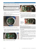
Using e-clip or needle nose pliers, remove the retaining clip from
3.
the inside of the pipe (
Figure 8
).
Attention:
To avoid component damage, removing the SE with needle nose pliers is
required. Please note that the SE can not be bent in less than a 2 foot radius
(
Figure 9
).
Removing the SE cable assembly
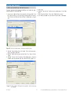
Figure 9.
Using needle nose pliers, gently pull the SE cable assembly out of
4.
the pipe. Remove the white base cartridge from the SE. To avoid
damaging the SE, do not bend the SE in less than a 2 ft. radius
(
Figure 9
).
Attention:
Damage to the SE and DT can occur when removing the plastic base
cartridge and heat shrink tubing from the SE (
Figure 8
).
Removing the retaining clip from inside of the pipe assembly
Figure 8.
Locate and open the
•
Gradient Off tag
which is attached to the new
SE. Record the gradient information and place it in a safe place. The
Gradient value will be entered into the configuration software Fac-
tory tab window after installation (Step 5 in next section).
Remove the black rubber plug from the end of the new SE.
•
Install the SE. There are two methods you can use to install the
5.
SE:
Roll the SE off the spool and directly into the pipe.
•
Uncoil the SE and gently feed it into the pipe by hand.
•
Light pressure and twisting may be required to install the SE into
the pipe. If the SE is bent or kinked, functionality and or breakage
will occur which will render the SE unrepairable.
Secure the SE with the retaining clip you removed in step 2 and
6.
reconnect the pipe to the instrument housing. Continue with
“
Replacing the transmitter electronics boards
”.
Attention:
If PC boards are in the housing, be sure you disconnect the SE and
DT cables first. When removing the pipe from the housing, damage
to the DT cable SE connections may occur if proper care is not taken
(
Figure 7
).
Remove the SE and DT cable connections first, See Removing the
1.
transmitter electronics boards.
Slowly unscrew the pipe from the housing. Be aware of possible
2.
damage to the DT and SE connectors when performing this step
(
Figure 7
).
SE and DT connector locations
Figure 7.
Removing and replacing the ME/SE


