Page 506
this is not possible, or a fi nal rotation
check is being performed:
1. Jog the motor briefl y.
2. Observe rotation as the unit comes
to a stop.
3. Rotation should be in the direction of
the arrow.
If the motor operates in the wrong
direction:
1. Interchange any two leads on a
three phase motor.
2. On a single phase motor,
change the leads as indicated on the
connection box cover. Some single
phase motors may not be reversible.
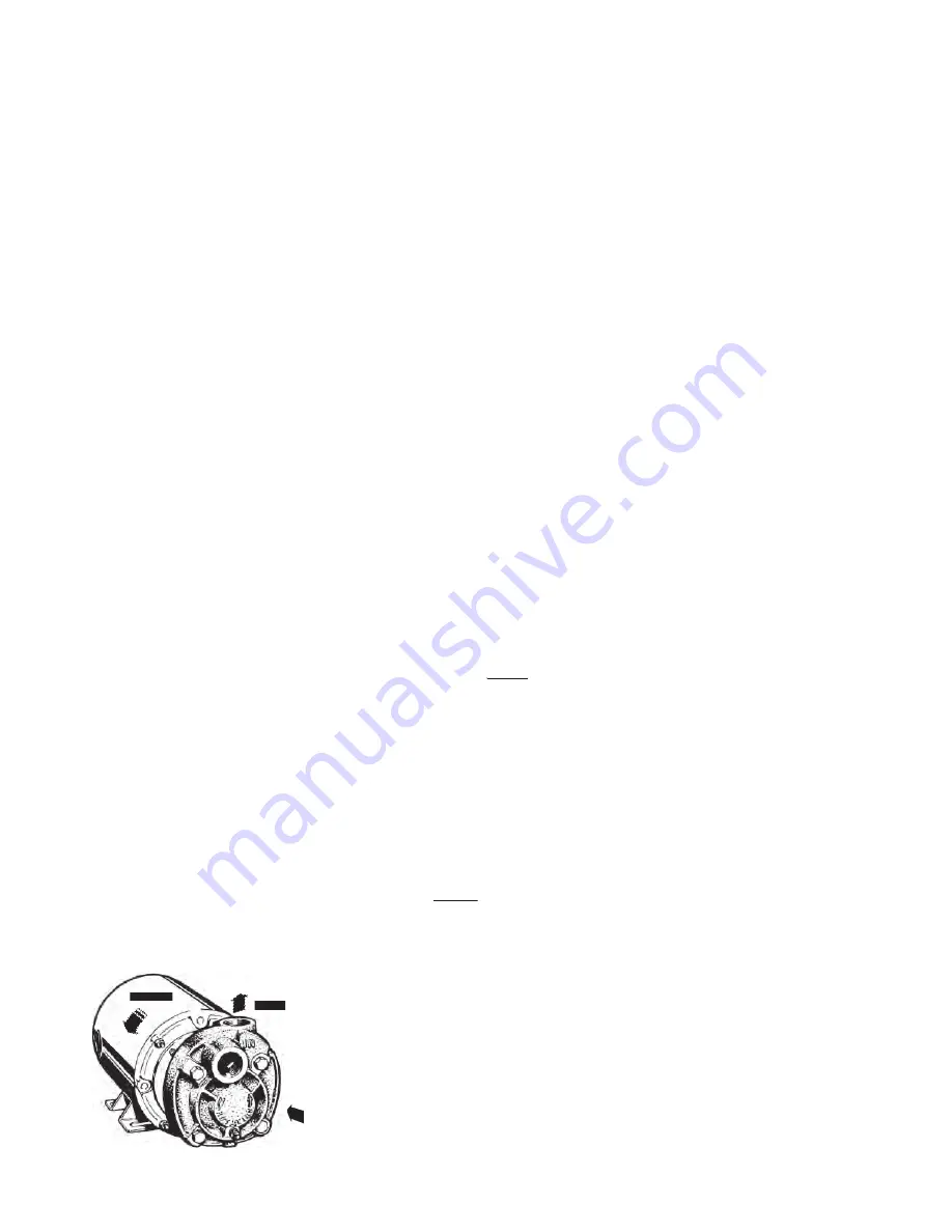
3B Inlet and Outlet Locations
(Refer to Figure 3-1)
The pump inlet is located on the end
farthest from the motor. The discharge
or “outlet” can be on the top, side, or
bottom depending on the model and
construction of the pump. Normal
discharge position is on top.
3C Foreign Material
All regenerative turbine pumps have
close running clearances in order to
maintain effi ciency. Take extra precau-
tions to insure that no foreign material
larger than 25 microns or .001 inches
is allowed to pass through the pump.
Even particles of this size can dam-
age the pump if allowed to continue.
Regenerative turbine pumps are not
designed for slurries.
Large particles, weld spatter, and other
material found in new
piping systems will bend the impeller
vanes and can sometimes lock up the
pump. If a new pump does not operate
properly, the fi rst thing to check for is
damage from foreign material.
3D Electrical
It is important to be aware of and fol-
low the appropriate local and national
electrical codes. Do not make wiring
alterations that can affect motor rotation
without reconfi rming correct rotation.
Select starter heaters and wiring for the
maximum current the motor can use
at full service factor loads. Regenera-
tive turbine pumps will typically use
extra power for a period until they run
in. This can take three to four weeks
depending on the duty cycle. During
this period, impellers are fi nding their
hydraulically balanced position.
3E Adjustments
No adjustments are required or advis-
able on new pumps. Because of
the close fi ts in regenerative turbine
pumps, it is not uncommon for the
pump to be diffi cult to turn over by hand
after they have been allowed to dry
out inside. New pumps from the fac-
tory are tested using rust inhibitors to
preclude this possibility. Onsite system
fl ushing may remove these inhibitors
and subject the pump to the risk of
lock up, if it is allowed to dry out. In this
case, do the following:
1. Fill the pump with fl uid.
2. Loosen the thrubolts exactly
exactly one
turn.
3. Jog the pump momentarily
using the on/off buttons if so
equipped.
4. This should “break” the impeller
loose without damage, unless for-
eign material has entered the pump.
5. If possible, spin the pump (or oper-
ate with minimal or zero discharge
pressure) while the thrubolts are
retightened exactly
exactly one turn.
This will fl ush residue from the close
fi tting impeller surfaces.
Because of the large areas of close
fi tting surfaces inside these pumps,
it takes only microscopic residue to
produce resistance to rotation. Once
loosened, this material is quickly dis-
persed and the impellers will fi nd their
hydraulic center. If these procedures
have been followed, no damage will
have resulted from "breaking loose" the
impeller.
3F Cooling Water
When the pump is used to pump hot
fl uids, consideration should be given
to cooling the seals and/or selecting
materials that will give satisfactory seal
life. The actual temperature at the seal
faces, the most critical area, will always
exceed the surrounding fl uid tempera-
ture. If seal fl ushing lines have not
been installed, heat can build up in the
seal faces to a degree that may destroy
the fl uid fi lm necessary to prevent rapid
wear. In some cases it is necessary to
cool the seal fl ushing fl uid. Refer to the
seal manufacturers charts for guidance
or to selection data in the MTH catalog
anytime fl uids can reach or exceed
their boiling point.
3G Priming
Pumps should not be operated
unless they are completely fi lled
with liquid. Damage to parts of the
pump that depend on liquid for their
lubrication can occur. Impellers can
seize quickly when a pump is run dry.
Without lubrication, seal faces can be
damaged from heat buildup.
Pumps can be easily primed with a
vacuum pump. An ejector or liquid ring
vacuum pump is recommended for this
purpose because they are not dam-
aged if liquid enters them.
Connect the vacuum line to the dis-
charge side of the pump, either in the
discharge opening or the drain tap. A
foot valve is not necessary when this
kind of device is used.
When a vacuum pump is not practical,
a foot valve in the suction inlet can be
used to prevent liquid from running out.
The pump and suction line can then
be fi lled completely from an outside
source. A vent opening will be neces-
sary during fi lling to let air escape. A
tight foot valve will keep the pump
constantly primed so that automatic
operation is possible. The valve should
be inspected regularly to see that it
does not develop leaks which would
allow the pump to run dry.
Optional self-priming casings are avail-
able for MTH pumps allowing priming
when a vacuum pump or foot valve is
not practical. Refer to specifi c literature
for details.
There are four components to the self
primer:
Figure 3-1
Inlet


