Section
T51 • E51
Page 512
Dated
February 2014
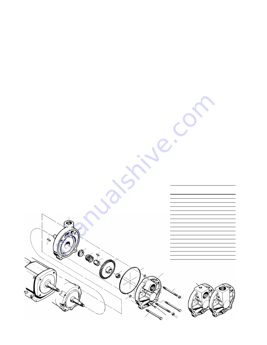
C15 - P15 CLOSE
COUPLED PUMP
Figure 4-11
23A
125
12
1
23
11
15
7
8
19
20
18
2
14
C15
P15
NAME/DESCRIPTION
PART
NO. QTY.
Motor Bracket
1
1
Cover
2
1
“O” Ring/Casing
7
1
“O” Ring/Guide Rod
8
4
Impeller
11
1
Seal Rotating Element
12
1
Seal Stationary Seat
125
1
Drive Sleeve/Impeller Drive
14
1
Impeller Nut
15
1
Guide Rod (Qty. 4 on Stainless Steel) 18
2
ThruBolt (Qty. 0 on Stainless Steel)
19
2
Nut (Qty. 4 on Stainless Steel)
20
2
Pipe Plug/Drain
22
1
Optional Vent/Port Plug*
22A
1
Key/Impeller Drive
23
1
Key/Sleeve Drive
23A
1
cracks and nicks. Scratches that
might be ignored elsewhere can
produce leakage if they are on seal
carbons and seat wearing surfaces.
Cleanliness is imperative when work-
ing with mechanical seals. Almost
unnoticeable particles between seal
faces can be, and often are, the
cause of early seal failures.
Check the impeller, it is designed to
float. It should slide easily on the
shaft. As long as it can be moved on
the shaft by hand, it is loose enough.
If the impeller can be rocked or
wobbled, it is too loose and must be
replaced.
Check the shaft for galling, pitting,
and corrosion. If the shaft is heavily
corroded where the seal comes in
contact with it, the motor shaft must
be replaced. Surface corrosion must
be removed so that seals can slide
freely during assembly. The shaft
diameter should be no smaller than
.002” below the nominal fractional
seal sizes. Remove any nicks or
burrs which may have occurred
during disassembly. Re-clean parts
as necessary.
4F Reassembly (C3 and P3)
All parts should be visually inspected
and cleaned or replaced as outlined
in 4D above.
1. The seal seat (#125) must be in-
stalled in the motor bracket before
the bracket is installed on the mo-
tor. To install the seat:
a. Place the motor bracket face up
on a flat surface.
b. Carefully press the seat,
smooth side up, into the seat
cavity of the motor bracket. To
make the installation of the seat
easier, apply a thin coating
of compatible lubricant to the
elastomer portion of the seat
prior to installation. Care must
be taken not to damage the
seat face. Thumb pressure is
usually sufficient to install the
seat.
2. Install the motor bracket.
a. Make sure the locking collar is
positioned on the motor shaft.
b. While holding the motor bracket
with the outlet port facing up,
slide the bracket over the two
(2) studs on the motor face.
c. Slide the bracket back until
the feet are resting against the
motor face. Light tapping may
be necessary to seat the motor
bracket in the proper position.
d. Install the four (4) “O” rings (#8)
on the two studs. This will help
hold the bracket in place during
the remainder of the assembly
operation.
3. Install the shaft sleeve and rotat-
ing element as a unit.
a. Place the sleeve in an upright
position with the smaller end
facing up.
b. Lubricate the shaft sleeve and
rotating element.
c. Be sure to install a key (#23A)
in the motor shaft before
installing the sleeve and seal
assembly.
d. Holding the element assembly
between the thumb and index
finger of both hands, refer to
Figure 4-13, slide the assembly
over the sleeve until the spring
holder rests against the shoul-
der of the sleeve.
e. The element must slide freely
up and down on the sleeve. It
Optional Cover Configurations
22A Not Shown
*Serial Number Specific
Contact factory for size
22


