2-12
Hardware Setup
MS-S1311
Power Supply
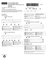
System Power Connector: JPWR3
This connector allows you to connect a power supply. To connect to the power
supply, make sure the plug of the power supply is inserted in the proper orienta
-
tion and the pins are aligned. Then push down the power supply firmly into the
connector.
13
.+
3.3
V
1.+
3.3
V
14
.-1
2V
2.+
3.3
V
15
.G
ro
un
d
3.G
ro
un
d
16
.P
S-
O
N
#
4.+
5V
17
.G
ro
un
d
5.G
ro
un
d
18
.G
ro
un
d
6.+
5V
19
.G
ro
un
d
7.G
ro
un
d
22
.+
5V
10
.+
12
V
20
.-5
V
8.P
W
R
O
K
23
.+
5V
11
.+
12
V
21
.+
5V
9.5
VS
B
24
.G
ro
un
d
12
.+
3.3
V
CPU Power Connector: JPWR1
This connector provides 12V power output to the onboard CPU.
7.+
12
V
3.G
ro
un
d
5.+
12
V
1.G
ro
un
d
8.+
12
V
4.G
ro
un
d
6.+
12
V
2.G
ro
un
d
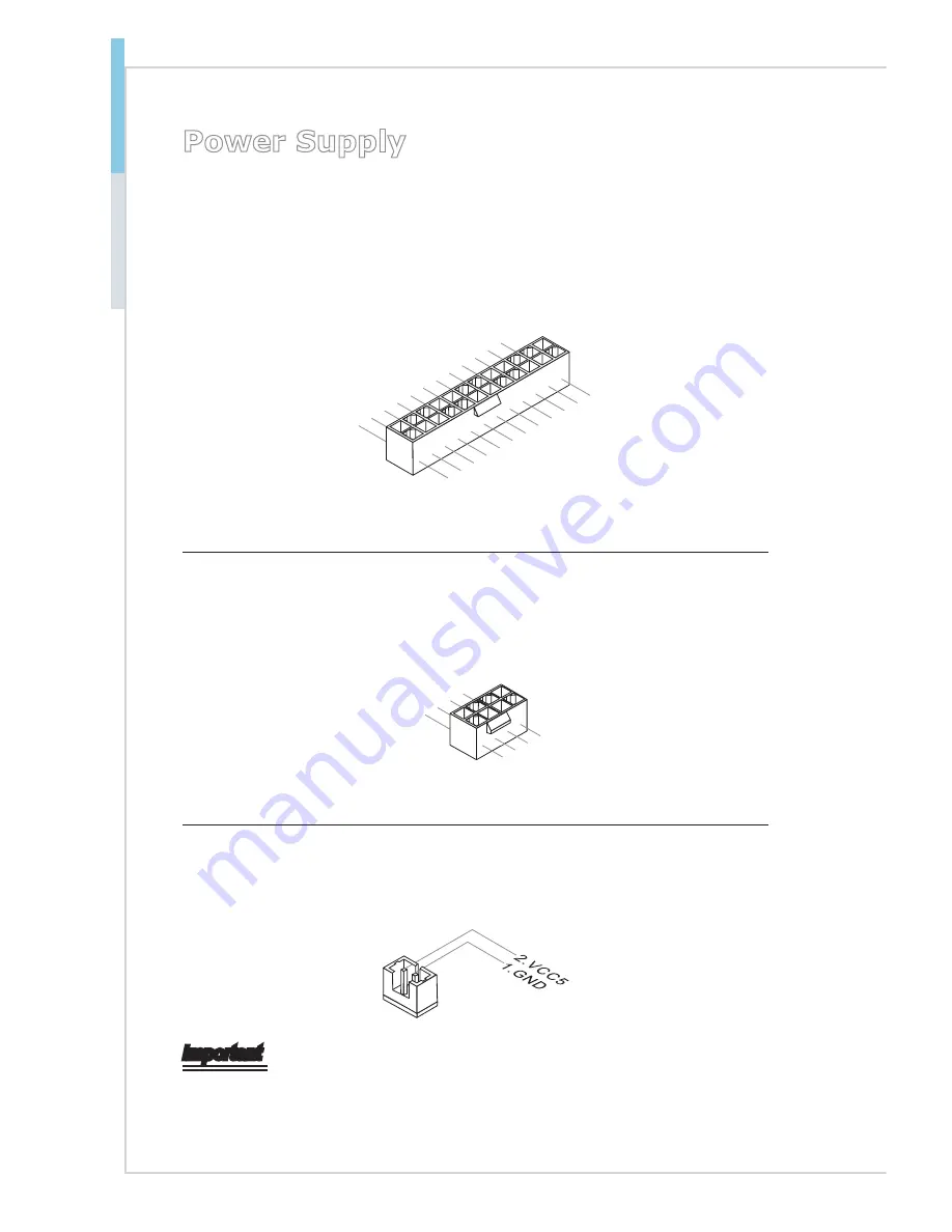
SATA DOM Power Connector: JSDOMPWR1
This connector provides power to the SATA DOM devices.
Important
Make sure that all power connectors are connected to the power supply to ensure
stable operation of the motherboard.
Summary of Contents for MS-S1311
Page 1: ...i MS S1311 v1 X Server Board...
Page 10: ......
Page 15: ...1 5 MS S1311 Motherboard Layout...
Page 16: ......
Page 26: ...2 10 Hardware Setup Storage Storage Port Location...
Page 44: ...3 6 BIOS Setup Advanced Boot Feature SOL Setting This setting enables disables the SOL setting...
Page 51: ...3 13 MS S1311 H W Monitor This menu shows the hardware monitor status Voltage Status...
Page 52: ...3 14 BIOS Setup Fan Status Temperature Status...
Page 53: ...3 15 MS S1311 Intel RC Setup...
Page 59: ...3 21 MS S1311 Server ME Configuration This menu displays the ME subsystem information...
Page 68: ......