background image

Chapter 4

4-10

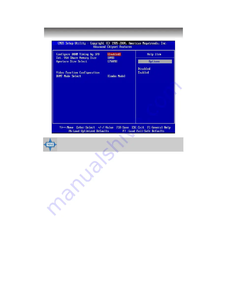
Advanced Chipset Features

Configure  DRAM  Timing  by SPD

Selects whether DRAM timing is controlled by the SPD (Serial Presence Detect)
EEPROM on the DRAM module. Setting options: [Disabled], [Enabled].

Int.  VGA  Memory  Size  Select

The field  specifies the size of  system  memory  allocated for video  memory.
Setting options: [Disabled], [1MB], [8MB].

Aperture  Size  Select

This setting controls  just how  much  system  RAM  can  be allocated  to  IGD
(internal graphic display) for video purposes. The  aperture is a portion of the
PCI memory address  range  dedicated to  graphics  memory  address space.
Host cycles  that hit the aperture range are forwarded to the IGD without any
translation. The option allows the selection of an aperture size of [128MB], and
[256 MB].

Video  Function  Configuration

This allows you to set the video functions.

DVMT  M ode  Select

Use the  field to  select  the mode  of  the digital  monitor you  use.  Setting
options: [Fixed Mode], [DVMT Mode], [Combo Mode].

MSI  Reminds You...

Change these settings only if you are familiar with the chipset.

Summary of Contents for Hetis 915

Page 1: ...User s Guide Hetis 915 G52 B6289X1 ...

Page 2: ...ations Operation of this equipment in a residential area is likely to cause harmful interference in which case the user will be required to correct the interference at his own expense Notice 1 The changes or modifications not expressly approved by the party re sponsible for compliance could void the user s authority to operate the equipment Notice 2 Shielded interface cables and AC power cord if a...

Page 3: ...rks All trademarks are the properties of their respective owners Intel and Pentium are registered trademarks of Intel Corporation PS 2 and OS 2 are registered trademarks of International Business Ma chines Corporation Windows 95 98 2000 NT XP are registered trademarks of Microsoft Corporation Netware is a registered trademark ofNovell Inc Award is a registered trademark of Phoenix Technologies Ltd...

Page 4: ...ny add on card or module 9 All cautions and warnings on the equipment should be noted 10 Never pour any liquid into the opening that could damage or cause elec trical shock 11 If any of the following situations arises get the equipment checked by a service personnel The power cord or plug is damaged Liquid has penetrated into the equipment The equipment has been exposed to moisture The equipment h...

Page 5: ... 10 ATX 20 Pin Power Connector ATX1 2 10 ATX 12V Power Connector JPW1 2 10 2 5 Front Panel 2 11 Audio Ports 2 11 USB Ports 2 11 IEEE 1394 Port Standard only 2 11 2 6 Rear Panel 2 12 Mouse Keyboard Connectors 2 12 Audio Port Connectors 2 13 VGA Port 2 13 Digital Panel Connector DVI Standard only 2 14 LAN RJ 45 Jack 2 15 USB Ports 2 15 Serial Ports 2 16 IEEE 1394 Port Standard only 2 16 S Video Out ...

Page 6: ...ion Procedures 3 4 1 Removing Cover 3 4 2 Installing HDD 3 5 3 Installing Optical Drive 3 6 4 Installing Card Reader Optional 3 7 5 Installing Memory Modules 3 8 6 Installing CPU 3 9 7 Installing CPU Cooler 3 10 8 Restoring Chassis Cover Installing Footstand 3 11 Chapter 4 BIOS Setup 4 1 Entering Setup 4 2 Selecting the First Boot Device 4 2 Control Keys 4 3 Getting Help 4 3 Main Menu 4 3 Default ...

Page 7: ... 5 Introduction to Realtek ALC880 5 1 Installing the Realtek HD Audio Driver 5 2 Installation for Windows 2000 XP 5 2 Software Configuration 5 4 Sound Effect 5 5 Audio IO 5 6 Mixer 5 9 Microphone 5 12 3D Audio Demo 5 13 Information 5 14 Using 2 4 6 8 Channel Audio Function 5 15 ...

Page 8: ... barebone is your best Slim PC choice Based on the all in one design idea Hetis provides 6 USB ports 2 full PCI slots for expansion With the fantastic appearance and small form factor it can easily be set anywhere The feature packed plat form also gives you an exciting PC experience ...

Page 9: ...slm_cpu_support php Chipset Intel 915GL chipset Supports FSB800 533MHz Supports DDR333 400 memoryinterface Integrated graphics controller Intel ICH6 chipset Hi Speed USB USB2 0 controller 480Mb sec 6 ports 2 Serial ATA 150 ports 2 channel Ultra ATA 66 100 bus Master IDE controller PCI Master v2 3 I O APIC Supports both ACPI and legacyAPM power management MainMemory Supports two unbuffered DIMM of ...

Page 10: ... Line Out x1 Mic In x1 RS Out x 1 C SOut x1 SS Out x 1 USB2 0 Ports x 4 RJ45 LAN Jack x1 ForStandardVersion IEEE 1394 6pins x1 DVI S Video Out RCAOut Audio 7 1 channel HDaudio codec RealtekALC880 LAN Intel Gigabit LAN On BoardGraphics Intel GMA 900 graphics Incredible graphics for photos videos and games High Definition TV HDTV displayresolution for a wonderful enter tainment experience Chassis Di...

Page 11: ... pink 5 HDD LED Headphone out green 6 Optical Drive Eject Close Button 2 2 x USB 2 0 Ports 7 Optical Drive optional 3 4 pin IEEE 1394 Port 8 Card Reader Drive optional 4 Power Button Power LED 1 2 System Configuration Standard Version ...

Page 12: ...ck 13 Support Bracket Spring 3 Ventilation Hole 14 RJ 45 LAN Jack 4 4 x USB 2 0 Ports 15 6 pin IEEE 1394 Port 5 PS 2 Mouse 16 Expansion Slots 6 PS 2 Keyboard 17 VGA Port 7 Serial Ports 18 Line out 8 DVI Port 19 Line in 9 S Video out 20 RCA out 10 Mic in 21 RS Out 11 SS Out 22 C S Out ...

Page 13: ... 1 1 6 Front View 1 Mic in pink 4 HDD LED Headphone out green 5 Optical Drive Eject Close Button 2 2 x USB 2 0 Ports 6 Optical Drive optional 3 Power Button Power LED 7 Card Reader Drive optional Lite Version ...

Page 14: ... Power On Off Switch 2 Power Jack 11 Support Bracket Spring 3 Ventilation Hole 12 RJ 45 LAN Jack 4 4 x USB 2 0 Ports 13 Expansion Slots 5 PS 2 Mouse 14 VGA Port 6 PS 2 Keyboard 15 Line out 7 Serial Ports 16 Line in 8 Mic in 17 RS Out 9 SS Out 18 C S Out ...

Page 15: ...Chapter 1 1 8 Connecting to External Devices ...

Page 16: ...W x94mm H Minimized screw structure Detachable bay housing Multiple ventilation holes 1 CPU Fan Ventilation Hole 4 Power Supply Ventilation Hole 2 System Ventilation Hole 5 System Ventilation Hole 3 System Fan Ventilation Hole 6 Release Button of Front I O Door ...

Page 17: ...CPU cooler and multiple ventilation holes for better cool ing effects The specially designed CPU cooler supports Intel LGA775 Prescott and Celeron D The following figures illustrate how the system fan effectively exhausts hot air through multiple ventilation holes CPU Fan Air Flow Direction Air In Air Out Air Out ...

Page 18: ...Getting Started 1 11 Power Supply Power Supply Fan Ventilation Hole System Fan Ventilation Hole front panel ...

Page 19: ...Air Flow Direction After the installation is completed please keep other objects away from the ventila tion hole at least 2 5cm and above Do not block the ventilation hole System Fan Power Supply Power Supply Fan front panel ...

Page 20: ...as well as how to setup the jumpers on the mainboard Also it provides the instructions on connecting the peripheal devices such as the mouse keyboard etc Whiledoing theinstallation be careful in holding thecom ponents and follow the installation procedures Introducing Mainboard ...

Page 21: ...PEN1 JPW1 JFP1 JBAT1 IDE1 ATX1 CR1 SATA1 SATA2 CPU_F3 Intel 915GL JCD1 Realtek ALC880 W83627THF Intel 82541P1 Intel ICH6 Winbond CHRONTEL CH7021A TEF CHRONTEL CH7307TC DEF VT6307 VIA AUDIO1 DIMM2 CON1 CPU_F2 DIMM1 AUDIO2 USB2 USB1 J1394 1 PCIE_1 Top VGA Port Bottom DVI Port J2 T M B Lin e In Line Ou t Mic S Video Out Top LAN Jack Bottom USB ports Top LAN Jack Bottom USB ports ...

Page 22: ...B Lin e In Line Ou t Mic CASE_OPEN1 JPW1 JFP1 JBAT1 IDE1 ATX1 CR1 SATA1 SATA2 CPU_F3 Intel 915GL JCD1 Realtek ALC880 W83627THF Intel 82541P1 Intel ICH6 Winbond AUDIO1 DIMM2 CON1 CPU_F2 DIMM1 AUDIO2 USB2 USB1 PCIE_1 Top LAN Jack Bottom USB ports Top LAN Jack Bottom USB ports MS 7137 V1 X Mainboard Lite Version ...

Page 23: ...rn off the power supply or unplug the power supply s power cord from grounded outlet first to ensure the safety of CPU Overclocking This motherboard is designed to support overclocking However please make sure your components are able to tolerate such abnormal setting while doing overclocking Any attempt to oper ate beyond product specifications is not recommended We do not guarantee the damages o...

Page 24: ...the bottom to protect the CPU con tact from damage Rotate it to make the pin 1 indicator yellow triangle in the right bottom corner 2 Take out the accompanying CPU Clip and rotate it for the same direction as the CPU Pin 1 indicator is in the left bottom corner land side cover MSI Reminds You 1 Confirm if your CPU cooler is firmly installed before turning on your system 2 Do not touch the CPU sock...

Page 25: ...e pins of socket reveal 7 Lift the load lever up and open the load plate 8 Correctly align the triangle of CPU Clip with the CPU chamfer and the square on the CPU Clip to the hook of the socket 9 Use your thumb and the middle fin gers to push the clips to release the CPU then press down the CPU with your index finger to allow the whole module to be installed onto the CPU socket 10 The CPU is insta...

Page 26: ...ggest you do not plug unplug the CPU too often 12 Press down the load lever lightly onto the load plate and then secure the lever with the hook under retention tab 11 Visually inspect if the CPU is seated well into the socket then remove the CPU Clip with 2 fingers Then cover the load plate onto the package Note If you want to uninstall the CPU align the 4 points see Point 8 for details again and ...

Page 27: ... supporting memory modules please visit http www msi com tw program products mainboard mbd pro_mbd_trp_list php DDR DIMM Slots DDR 1 2 Introduction to DDR SDRAM DDR DoubleData Rate SDRAM is similar toconventional SDRAM but doubles the rate by transferring data twice per cycle It uses 2 5 volts as opposed to 3 3 volts used in SDR SDRAM and requires 184 pin DIMM modules rather than 168 pin DIMM modu...

Page 28: ...ide of the DIMM slot will automatically close MSI Reminds You You can barely see the golden finger if the module is prop erly inserted in the socket DIMM Module Combination Install at least one DIMM module on the slots You can install either single or double sided modules in any order to meet your own needs Memory modules can be installed in any combination as follows S Single Side D Double Side S...

Page 29: ...nserted in the proper orientation and the pins are aligned Then push down the power supply firmly into the connector ATX 12V Power Connector JPW1 This 12V power connector is used to provide power to the CPU PIN SIGNAL 11 3 3V 12 12V 13 GND 14 PS_ON 15 GND 16 GND 17 GND 18 5V 19 5V 20 5V PIN SIGNAL 1 3 3V 2 3 3V 3 GND 4 5V 5 GND 6 5V 7 GND 8 PW_OK 9 5V_SB 10 12V ATX1 Pin Definition PIN SIGNAL 1 GND...

Page 30: ...atible devices You can plug the USB devices directly into these connectors IEEE 1394 Port For Standard Version The front panel provides one IEEE 1394 port This smaller one is designed for you to connect the IEEE 1394 device with external power The IEEE 1394 high speed serial bus complements USB by providing enhanced PC connectivity for a wide range of devices including con sumer electronicsaudio v...

Page 31: ...t USB Ports Keyboard LAN Jack Mouse Serial Port Serial Port DVI Port For Standard Version IEEE 1394 6pins For Standard Version S Video Out For Standard Version RS CS SS PIN SIGNAL DESCRIPTION 1 MouseDATA MouseDATA 2 NC Noconnection 3 GND Ground 4 VCC 5V 5 MouseClock Mouseclock 6 NC Noconnection Mouse Pin Definition PIN SIGNAL DESCRIPTION 1 KeyboardDATA Keyboard DATA 2 NC No connection 3 GND Ground...

Page 32: ...io devices Mic is a connector for microphones However there is an advanced audio application provided by RealtekALC880 tooffer support for 7 1 channel audiooperation and can turn rear audio connectors from 2 channel to 4 5 1 7 1 channel audio Rear Speaker Out in 7 1CH 5 1CH Line Out Line In MIC Center Subwoofer Speaker Out in 7 1CH 5 1CH Side Surround Out in 7 1CH VGA Port Pin Definition PIN SIGNA...

Page 33: ...onnect an LCD monitor The DVI connector provides a high speed digital interconnection between the computer and its display device To connect a LCD monitor simply plug your monitor cable into the DVI connector on the mainboard and make sure that the other end of the cable is properly connected to your monitor refer to your monitor manual for more information LCD Monitor 1 24 17 8 Pin 1 2 3 4 5 6 7 ...

Page 34: ...gle Local Area Network LAN This Giga bit LAN enables data to be transferred at 1000 100 or 10Mbps You can connect a network cable toit Giga bit LAN Pin Definition PIN SIGNAL DESCRIPTION 1 D0P Differential Pair0 2 D0N Differential Pair 0 3 D1P Differential Pair1 4 D2P Differential Pair2 5 D2N Differential Pair 2 6 D1N Differential Pair 1 7 D3P Differential Pair3 8 D3N Differential Pair 3 RJ 45 LAN ...

Page 35: ...erminal Ready 5 GND Ground 6 DSR DataSetReady 7 RTS Request T o Send 8 CTS ClearTo Send 9 RI Ring Indicate Serial Port Pin Definition 9 Pin Male DIN Connector 1 2 3 4 5 6 7 8 9 IEEE 1394 Port For Standard Version The back panel provides one standard IEEE 1394 port The standard IEEE 1394 port connects to IEEE 1394 devices without external power The IEEE 1394 high speed serial bus complements USB by...

Page 36: ...n the mainboard and the other end to the video input connector on your TV or video device Some TVs and video devices may support such kind of input connector For the correct connection please refer to the TVs and video devices manuals for more information S Video Out TV Projector TV1 Connector TV Projector RCA Connector TV1 Standard only You can connect a TV or video device toTV1 connector for vid...

Page 37: ...00 controller that provides PIO mode 0 4 Bus Master and Ultra DMA 33 66 100 function The connectors on the mainboard allows you to connect to the IDE devices HDD CD ROM 2 7 Connectors IDE1 Card Reader Connector CR1 The mainboard provides a connector to connect the Card Reader on the Front Panel CR1 ...

Page 38: ... SATA2 Pin Definition 1 7 Fan Power Connectors CPU_F2 CPU_F3 The CPU_F2 processor fan and CPU_F3 system fans support system cooling fan with 12V It supports three pin head connector When connecting the wire to the connectors always take note that the red wire is the positive and should be connected to the 12V the black wire is Ground and should be connected to GND The mainboard has a ADT7467 chips...

Page 39: ...to GND 6 PWR_SW_P PowerSwitchhigh reference pull up 7 RST_SW_P Reset Switch high reference pull up 8 PWR_SW_N PowerSwitch lowreferencepull down to GND 9 RSVD_DNU Reserved Donot use JFP1 Pin Definition Front Panel Connectors JFP1 The mainboard provides one front panel connector for you to connect to the front panel switches and LEDs JFP1 is compliant with Intel Front Panel I O ConnectivityDesign Gu...

Page 40: ... 21 Internal Speaker Connector CON1 This connector is used to connect the built in speaker RCA out Connector J2 For Standard Version The mainboard provides a TV out connector for you to connect to a TV or video device J2 CON1 ...

Page 41: ...nal battery to keep the system configuration data With the CMOS RAM the system can automatically boot OS every time it is turned on If you want to clear the system configuration use the JBAT1 Clear CMOS Jumper to clear data Follow the instructions below to clear the data MSI Reminds You You can clear CMOS by shorting 2 3 pin while the system is off Then return to 1 2 pin position Avoid clearing th...

Page 42: ...iser Cards allows you to insert two expansion card You can insert any type of PCI cards to meet your needs When adding or removing expansion cards make sure that you unplug the power supply first Meanwhile read the documentation for the expansion card to make any necessary hardware or software settings Riser Card PCI Express Slot PCIE_1 For Riser Card Use Only PCI Express slot ...

Page 43: ... Assembly 3 1 This chapter provides you with the installation procedures of Midas barebone It is useful for you to read the information of mainboard setup before assembling the whole system 3 System Assembly ...

Page 44: ...how you how to install CPU Card Reader HDD Optical Drives and CPU Cooler Installation Tools Screws Two types of screws are used in assembling the barebone round headed screw thumb screw Round headed screw This type of screw is used to attach the HDD and card reader to the tray Screw Driver Gloves 3 1 Overview Thumb screw This type of screw is used to fasten the chassis cover to the chassis ...

Page 45: ...please check the items listed below for basic system operation The Footstand and the CPU cooler are included in the package other items are optional CPU Cooler Footstand IDE or SATA HDD Optional Optical Drive Optional CPU Optional DDR SDRAM Optional Card Reader Optional ...

Page 46: ...o screws on the backplane with hands Remove the chassis cover Press the level on the support bracket spring to release it 1 Removing Cover 3 2 Installation Procedures Unlock the screw on the front panel to release the drive cage ...

Page 47: ...ide Pull the HDD tray forwards to remove it from the chassis Put the HDD in the HDD tray and use 4 screws to fix it on both sides Connect the cable and the power cord to the HDD then put the HDD tray back to secure it on the drive cage 2 Installing HDD ...

Page 48: ... brackets outwards on the both sides to release Insert the optical drive and push the lock brackets back to fix it Connect the cable and the power cord to the optical drive then restore the drive cage Lock the screw on the front panel to fix the drive cage ...

Page 49: ...e card reader with two screws Use the screwdriver to unlock the card reader cage Insert the card reader into the cage with 15 degree angle 4 Installing Card Reader Optional Restore the card reader back and connect the cable to the CR1 connec tor on the mainboard ...

Page 50: ...Chapter 3 3 8 Locate the DIMM slots 5 Installing Memory Modules Insert the DIMM vertically into the slot Note The DIMM has only one notch onthecenter ofmodule Itwillonlyfit in the right direction ...

Page 51: ...from the socket and raise it up then lift up the cover Close the cover and the lever to complete the installaton 6 Installing CPU Put the CPU onto the socket Note Make sure the pinsare completely embeddedinto the socket The CPUcan only fit inthe correct direction ...

Page 52: ...Chapter 3 3 10 Connect the CPU cooler s power cord to the connector on the mainboard 7 Installing CPU Cooler Place the CPU cooler onto the CPU socket and secure the four screws ...

Page 53: ... 8 Restoring Chassis Cover Installing Footstand Restore the chassis cover Lock the chassis cover with the screws Put the PC on the footstand or lay on the rubber foots Horizontal type Tower type Restore the support bracket ...

Page 54: ...OS category described in this chap ter are under continuous update for better system performance Therefore the description may be slightly dif ferent from the latest BIOS and should be held for reference only 2 While booting up the BIOS version is shown in the 1st line appearing after the memory count It is usually in the format example A7137IMS V1 0BH 01 23 05 where 1st digit refers to BIOS maker...

Page 55: ...etup utility by pressing F11 When the same message as listed above appears on the screen press F11 to trigger the boot menu The POST messages might pass by too quickly for you to respond in time If so restart the system and press F11 after around 2 or 3 seconds to activate the boot menu similar to the following The boot menu will list all the bootable devices Select the one you want to boot from b...

Page 56: ...ices and the system Move to the previous item Move to the next item Move to the item in the left hand Move to the item in the right hand Enter Select the item Esc Jumps to the Exit menu or returns to the main menu from a submenu Increase the numeric value or make changes Decrease the numeric value or make changes F6 Load Optimized Defaults F7 Load Fail Safe Defaults F10 Save all the CMOS changes a...

Page 57: ...specify your settings for integrated peripherals Power Management Features Use this menu to specify your settings for power management PNP PCI Configurations This entry appears if your system supports PnP PCI H W Monitor This entry shows the status of your CPU fan warning for overall system status Load Fail Safe Defaults Use this menu to load the default values set by the BIOS vendor for stable sy...

Page 58: ...ult values set by the mainboard manufacturer specifically for optimal performance of the mainboard BIOS Setting Password Use this menu to set the password for BIOS Save Exit Setup Save changes to CMOS and exit setup Exit Without Saving Abandon all changes and exit setup ...

Page 59: ... Day of the week from Sun to Sat determined by BIOS Read only month The month from Jan through Dec date The date from 1 to 31 can be keyed by numeric function keys year The year can be adjusted by users Time HH MM SS This allows you to set the system time that you want usually the current time The time format is hour minute second IDE Primary Secondary Third Master Slave Press or to select the har...

Page 60: ...ility that monitors your disk status to predict hard disk failure This gives you an opportunity to move data from a hard disk that is going to fail to a safe place before the hard disk becomes offline Settings Auto Enabled Disabled System Information Press Enter to for the sub menu of each item Market Name Model Name This item shows the the PC Mainboard names read only Total System Memory BIOS Ver...

Page 61: ...function at all times The only time when you need to disable it is when you want to update the BIOS After updating the BIOS you should immediately re enable it to protect it against viruses Setting options Enabled Disabled NX Support NX No eXecute Support function is designed for memory buffer overflow protection it can prevent viruses from proliferating Settings Enabled Disabled C1E Support When ...

Page 62: ...e operating system Boot From Other Devices Setting the option to Yes allows the system to try to boot from other devices if the system fails to boot from the 1st 2nd 3rd boot device Set tings are Yes No MSI Reminds You Available settings for 1st 2nd 3rd Boot Device vary depending on the bootable devices you have installed For example if you did not install a floppy drive the setting Floppy will no...

Page 63: ...an be allocated to IGD internal graphic display for video purposes The aperture is a portion of the PCI memory address range dedicated to graphics memory address space Host cycles that hit the aperture range are forwarded to the IGD without any translation The option allows the selection of an aperture size of 128MB and 256 MB Video Function Configuration This allows you to set the video functions...

Page 64: ... Enabled Disabled Onboard LAN Option ROM The item enables or disables the initialization of the onboard LAN Boot ROMs during bootup Selecting Disabled will speed up the boot process Setting options Enabled Disabled OnBoard IEEE1394 Controller Optional This setting is used to enable disable the onboard IEEE 1394 controller Setting options Enabled Disabled Onboard Audio Controller This item is used ...

Page 65: ... B Selecting Auto allows AMIBIOS to automatically determine the correct base I O port address Settings 3F8 IRQ4 2F8 IRQ3 3E8 IRQ4 2E8 IRQ3 and Disabled ATA IDE Configuration Configure SATA as These 2 items allow you to select the ATA IDE and SATA configuration Select Disabled in ATA IDE Configuration if you want to disable both ATA IDE configuration Select Compatible or Enhanced to use the IDE S A...

Page 66: ... 2 For the setting options of Configure SATA as select IDE if you want to have SATA as IDE function Select AHCI to allow the SATA to have Ad vanced Host Controller Interface AHCI feature which supports improved serial ATA disk performance with native command queuing native hot plug ...

Page 67: ...STR The S3 sleep mode is a lower power state where the informa tion of system configuration and open applications files is saved to main memory that remains powered while most other hard ware components turn off to save energy The information stored in memory will be used to restore the system when a wake up event occurs Auto BIOS determines the best setting automatically Re Call VGA BIOS from S3 ...

Page 68: ...tus before power failure or interrupt occurred Wakeup Event Setup Press Enter and the following sub menu appears Resume From S3 By USB Device The item allows the activity of the USB device to wake up the system from S3 Suspend to RAM sleep state Setting options Disabled Enabled PowerOn by Keyboard This controls how and whether the PS 2 keyboard is able to power on the system If you choose Password...

Page 69: ... off state Resume by PCI PCI E Device This controls how and whether the system can be powered on by the devices installed on PCI PCI E slots Setting options Disabled Enabled Resume by RTC Alarm This is used to enable or disable the feature of booting up the system on a scheduled time date from the S3 S4 and S5 power off state Setting options Disabled Enabled ...

Page 70: ...er Priority This setting specifies which VGA card is your primary graphics adapter Set ting options are IGD The system initializes the IGD internal graphic display first for 915G only PCI IGD The system initializes the PCI graphic card first If a PCI graphic card is not available it will initialize the IGD for 915G only PCI Latency Timer This item controls how long each PCI device can hold the bus...

Page 71: ...tting of the field will automatically return to Enabled later Settings Enabled Reset Disabled PC Health Status Press Enter and the following sub menu appears CPU System FAN Control This item enables or disables the Smart Fan feature Smart Fan is an excellent feature which will adjust the CPU System fan speed automatically depending on the CPU System current temperature avoiding the overheating to ...

Page 72: ...and press Enter You may also press Esc to abort the selection and not enter a password To clear a set password just press Enter when you are prompted to enter the password A message will show up confirming the password will be disabled Once the password is disabled the system will boot and you can enter Setup without entering any password When a password has been set you will be prompted to enter ...

Page 73: ...er specifically for optimal performance of the mainboard The Fail Safe Defaults are the default values set by the BIOS vendor for stable system performance When you select Load Fail Safe Defaults a message as below appears Pressing Y loads the BIOS default values for the most stable minimal system performance When you select Load Optimized Defaults a message as below appears Pressing Y loads the d...

Page 74: ...880 chip which provides support for 8 channel audio output including 2 Front 2 Rear 2 Side 1 Center and 1 Subwoofer channel ALC880 allows the board to attach 2 4 6 or 8 speakers for better surround sound effect The section will tell you how to install and use 2 4 6 or 8 channel audio function on the board 5 5 ...

Page 75: ...P you must install Windows XP Service Pack1 or later before installing the driver The following illustrations are based on Windows XP environment and could look slightly different if you install the drivers in different operating systems 1 Insert the companion CD into the CD ROM drive The setup screen will auto matically appear 2 Click Realtek HD Audio Driver Click here MSI Reminds You The HD Audi...

Page 76: ...Introduction to Realtek ALC 880 5 3 4 Click Finish to restart the system 3 Click Next to install the Realtek High Definition Audio Driver Click here Click here Select this option ...

Page 77: ...to use the 2 4 6 or 8 channel audio feature now Click the audio icon from the system tray at the lower right corner of the screen to activate the HD Audio Configuration It is also available to enable the audio driver by clicking the Azalia HD Sound Effect Manager from the Control Panel ...

Page 78: ...move a preset EQ setting There are also other pre set equalizer models for you to choose by clicking Others under the Equalizer part Here it provides the Karaoke function which will automatically remove human voice lyrics and leave melody for you to sing the song You may use the up arrow and down arrow button to raise lower the key and press the lower button to remove the human voice Raise the key...

Page 79: ...before for each jack they are not limited to perform certain functions Instead each jack is able to be chosen to perform either output ex playback function or input ex Recording function all by your own choices Please follow the steps below to use it 1 Plug the speakers in any available jack 2 Dialogue connected device will pop up for your selection Please select the device you have plugged in If ...

Page 80: ...le and the dialogue connected device pops up the default setting of blue jack is Line in Check the headphone anyway then click OK You should notice the icon beside blue jack remains the same without any change and the error message pops Pop screen check list 2CH Speakers configutaion check the Front Speaker Out anyway 4CH Speakers configuration check the Front Speaker Out Rear Speaker Out anyway 6...

Page 81: ...d make testing sound If any speaker fails to make sound then check whether the cable is inserted firmly to the connector or replace the bad speakers with good ones Or you may click the auto test button to test the sounds of each speaker automatically Subwoofer Front Right Rear Right Center Front Left Rear Left Side Left Side Right ...

Page 82: ... panel or front panel This feature is very helpful when 2 people are using the same computer together for different purposes Click the button and the Mixer ToolBox menu will appear Then check the Enable playback multi streaming and the Update preferred playback device automatically items and click OK to save the setup MSI Reminds You Before set up please make sure the playback devices are well plu...

Page 83: ...m the rear panel which is the default setting Then you must to select the Realtek HD Audio front output from the scroll list first and use a different program to play the second audio source for example use Winamp to play MP3 files You will find that the second audio source MP3 music will come out from the Line Out audio jack of Front Panel ...

Page 84: ...in this case If you d like to connect your microphone to the front audio panel please select the Mic in at front panel Pink from the scroll list after connecting microphone to the front audio panel MSI Reminds You Only the speakers that plugged into the Line Out jack the green ne on the back panel will be functional when you intend to listen to the audio that has been recorded from the microphone ...

Page 85: ...lect the Noise Suppression to remove the possible noise during recording or select Acoustic Echo Cancelltion to cancel the acoustic echo druing recording Also please use the drop down list to choose the recording source from Realtek HD Audio real input or Realtek HD Audio front input ...

Page 86: ...tek ALC 880 5 13 3D Audio Demo In this tab you may adjust your 3D positional audio before playing 3D audio applications like gaming You may also select different environment to choose the most suitable environment you like ...

Page 87: ...io Controller Audio Codec You may also select the language of this utility by choosing from the Language list Also there is a selection Show icon in system tray Switch it on and an icon will show in the system tray Right click on the icon and the Audio Accessories dia logue box will appear which provides several multimedia features for you to take advantage of ...

Page 88: ... setting in software utility n 2 Channel Mode for Stereo Speaker Output Refer to the following diagram and caption for the function of each phone jack on the back panel when 2 Channel Mode is selected Back Panel 3 1 2 6 4 5 1 Line In 2 Line Out Front channels 3 MIC 4 Line Out Rear channels but no functioning in this mode 5 Line Out Center and Subwoofer channel but no functioning in this mode 6 Sid...

Page 89: ...connector and two speakers to the real chan nel Line Out connector 3 1 2 6 4 5 1 Line In 2 Line Out Front channels 3 MIC 4 Line Out Rear channels 5 Line Out Center and Subwoofer channel but no functioning in this mode 6 Side Surround Out Side channels but no functioning in this mode 4 Channel Analog Audio Output ...

Page 90: ...Out connector two speakers to the rear channel and two speakers to the cen ter subwoofer channel Line Out connectors 6 Channel Analog Audio Output 1 Line In 2 Line Out Front channels 3 MIC 4 Line Out Rear channels 5 Line Out Center and Subwoofer channel 6 Side Surround Out Side channels but no functioning in this mode 1 2 6 4 5 3 ...

Page 91: ... the rear channel two speakers to the center subwoofer channel Line Out connectors and two speakers to the side channel Line Out connectors 8 Channel Analog Audio Output 1 Line Out Side channels 2 Line Out Front channels 3 MIC 4 Line Out Rear channels 5 Line Out Center and Subwoofer channel 6 Side Surround Out Side channels 1 2 6 4 5 3 ...

Reviews: