USER’S GUIDE
P
O
WER
M
ATE
2000
S
ERIES
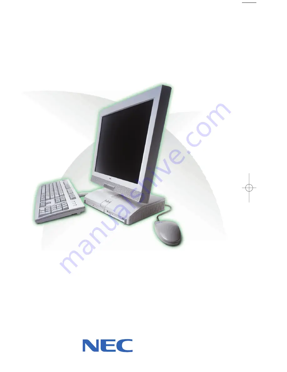
When Space is at a Premium and Flexibility is Key
U S E R ’ S G U I D E
O W E R
AT E
®
2 0 0 0 S
E R I E S
Part Number: 456-00133-000
456-00133-000 4/26/00 4:20 PM Page 1
Page 1: ...When Space is at a Premium and Flexibility is Key U S E R S G U I D E POWERMATE 2000 SERIES ...
Page 2: ...duct However actual performance of each such product is dependent upon factors such as system configuration customer data and operator control Since implementation by customers of each product may vary the suitability of specific product configurations and applications must be determined by the customer and is not warranted by NECC To allow for design and specification improvements the information...
Page 3: ...ontrol 1 8 PC Card Slots 1 8 Fan 1 8 Rear Features 1 8 Universal Serial Bus Ports 1 9 DC Power Connector 1 9 PS 2 Mouse Port 1 10 PS 2 Keyboard Port 1 10 VGA Monitor Connector 1 10 Printer Port 1 10 Serial Port 1 10 LAN Connector 1 11 Bottom Features 1 11 Memory Sockets 1 12 Password Clear Jumper 1 12 Microdesktop Chassis 1 12 System Overview 1 13 Hardware 1 13 Software 1 14 Preloaded Microsoft Op...
Page 4: ...5 Main Menu 3 7 Advanced Menu 3 12 Security Menu 3 17 Power Menu 3 20 Boot Menu 3 22 Exit Menu 3 24 Hard Drive Security 3 24 Establishing Hard Disk Drive Passwords 3 25 Changing Hard Disk Drive Passwords 3 26 Using Hard Disk Drive Password Protection 3 26 Moving the Hard Drive 3 27 FLASH Utility 3 27 NEC Application and Driver CD 3 28 NEC INFO Center 3 29 NEC OS Restore CD 3 31 System Board Jumper...
Page 5: ...ms 5 5 Keyboard Mouse Problems 5 5 CD ROM Drive Problems 5 6 Speaker Problems 5 7 How to Clean the Mouse 5 7 6 Getting Services and Support NECC Website 6 2 NECC FTP Site 6 3 Email Fax Technical Support Service 6 3 NECC Technical Support Services 6 4 A Setting Up a Healthy Work Environment Making Your Computer Work for You A 2 Arrange Your Equipment A 3 Adjust Your Chair A 4 Adjust Your Input Devi...
Page 6: ...Clock B 2 Input Output I O Features B 3 Video Memory B 3 Sound Controller B 4 Network Board B 4 Graphics Controller B 4 System Peripherals B 5 LCD Panel B 5 External Monitor B 6 Keyboard B 6 Mouse B 6 Diskette Drive B 7 Hard Drive B 7 CD ROM Drive B 8 PC Card Slots B 8 Speakers B 8 Dimensions B 9 System B 9 Keyboard B 9 Power B 9 Operating Environment B 9 Compliance B 10 Index Regulatory Statement...
Page 7: ...S Restore CD and Intel Pentium III Serial Number Control Utility The chapter also includes information for setting system jumpers Chapter 4 Adding Expansion Devices provides installation procedures for adding expansion devices such as USB devices PC cards memory upgrade modules external monitor and printer Chapter 5 Solving System Problems contains troubleshooting tips for solving simple problems ...
Page 8: ...otes have the following meanings Warnings alert you to situations that could result in serious personal injury or loss of life Cautions indicate situations that can damage the hardware or software Note Notes give important information about the material being described Names of keyboard keys are printed as they appear on the keyboard for example Ctrl Alt or Enter Text or keystrokes that you enter ...
Page 9: ...in the Release Notes is the result of extensive product testing Your system also comes with the NEC INFO Center online documentation on the NEC Application and Driver CD The NEC INFO Center is an online guide to your PowerMate system It provides information about the system through the following online modules Tour User s Guide Questions Solutions and Services In addition to the documentation that...
Page 10: ...1 Reviewing System Features Front Features Left Side Features Rear Features Bottom Features System Overview ...
Page 11: ...dix A Setting Up a Healthy Work Environment This chapter highlights system hardware and software features and describes system security features Front Features The following figures show the features on the front of the system unit and the front of the liquid crystal display LCD panel Brief descriptions of the features follow the figures PowerMate 2000 System A LCD Panel C System Unit B Power Slee...
Page 12: ...iskette Drive B CD ROM Eject Button G Diskette Eject Button C CD ROM Drive Lamp H Hard Drive Lamp D CD ROM Disc Emergency Eject I Power Lamp E Diskette Drive Lamp J Sleep Lamp LCD panel features A LCD Panel C Increase Brightness Level Button B Decrease Brightness Level Button ...
Page 13: ...ture if you plan to be away from your system for more than 15 minutes Do not hold the button in any longer than three seconds or you will turn off the system and possibly lose data Press any key or move the mouse to resume system operation at the point where you stopped it Power and sleep lamps The power lamp indicates if system power is on or off The sleep lamp lets you know if the system is oper...
Page 14: ...se brightness button and a decrease brightness button on the panel allows you to increase or decrease the brightness of the display The buttons provide eight levels of brightness The default brightness is maximum Note Powering off the system or unplugging the system from the power outlet changes any new brightness setting to the maximum default brightness Diskette Drive Use the diskette drive to c...
Page 15: ...e operates at different speeds depending on whether the CD you are using contains data or music This allows you to get your data faster and to see smoother animation and video A flashing amber activity lamp on the front of the drive indicates that the drive is reading data Press the tray button to open or close the CD ROM tray for loading or unloading a CD An emergency eject feature allows you to ...
Page 16: ...o Connectors The system unit has the following audio connectors Microphone in jack Use this jack to connect a microphone for recording audio information in your data files Line in jack Use this jack to connect a stereo audio device such as a stereo amplifier or a cassette for playback or recording Headphone jack Use this jack to connect an optional headphone set Plugging in the headphone set disab...
Page 17: ...g the system s capabilities Each type of PC card has a different function Using the PC card slots you can add a number of functions to the system with a variety of cards for example modem memory Small Computer System Interface A PC card is inserted into a PC card slot similar to inserting a diskette in a diskette drive Press the eject button to eject a PC card Removable slot covers keep foreign ma...
Page 18: ...ts allow you to easily and conveniently add plug and play USB devices without opening up the system You simply plug the USB device into a port You can connect up to 127 USB devices including a keyboard mouse monitor printer scanner or speaker set DC Power Connector The system operates with DC power supplied from the AC power adapter The adapter plugs into an AC power source and the DC power connec...
Page 19: ...r on the rear of the system unit Use this connector to connect an optional NEC MultiSync monitor NEC VistaScan monitor or other VGA compatible monitor with a 15 pin connector You can also attach a projector with a 15 pin connector to this connector The system supports simultaneous use of the LCD panel and an optional monitor connected to the VGA connector Printer Port Use this port to connect a pa...
Page 20: ...to connect a network cable to the internal 100Base TX 10Base T network board Bottom Features A panel on the bottom of the system unit covers the memory expansion sockets and the password clear jumper See Chapter 4 Adding Expansion Devices for information on removing the panel Bottom features A SO DIMM Socket 1 C SO DIMM Socket 0 B Password Clear Jumper ...
Page 21: ...ctual memory use dependent on video usage Password Clear Jumper Use the password clear jumper 7F4 to clear your password if you forgot it To clear and reset the password see Jumper Settings and Security Menu in Chapter 3 Microdesktop Chassis The NEC Microdesktop chassis conforms to NEC s Very Small Form Factor and Flat Panel Display Specification The microdesktop has the following features small s...
Page 22: ...onal sound effects It also provides wavetable synthesis Flashable ROM BIOS The system s ROM BIOS features system setup configuration Plug and Play support and flash support for economical BIOS upgrades System and Video Memory Your system comes with at least 64 MB of non ECC PC100 SDRAM and supports up to 512 MB of total system memory The memory uses DVMT technology which allows system memory to be...
Page 23: ...data loss or corruption you can restore your system to its original factory state or you can restore just the operating system and drivers You can also perform hard drive partitioning After restoring the operating system you can use the Application and Driver CD to install your applications drivers and NECC online documents NEC Application and Driver CD Your system comes an NEC Application and Dri...
Page 24: ...module to find possible solutions to system problems The Services module contains service information such as where to go on the Internet for help who to call for service and more A wide selection of drivers Drivers for hardware that is compatible with PowerMate series computers are provided with the original manufacturer s installation wizards to ensure correct installation Security The system ha...
Page 25: ...ive if the drive is removed and installed in another system The system does not prompt for hard drive passwords while the drive remains in the current system The passwords are written to the system BIOS and to the hard drive to ensure that the password protection travels with the hard drive in the event it is moved to another system See Hard Drive Security in Chapter 3 for additional information o...
Page 26: ...2 Setting Up the System Cable Connections Startup Shutdown Power Saving Operation System Care More Information ...
Page 27: ...for guidelines on configuring the LAN Connect the system AC adapter power cord to a surge protector recommended or a properly grounded wall outlet and to the DC power connector at the rear of the system unit NECC recommends connecting the AC adapter power cord to a surge protector to protect your system Startup Press the power button to turn on the system unit and LCD panel The power lamp lights g...
Page 28: ...amage to system components wake a system in sleep mode save and close any open applications exit Windows and power down the system 1 If the system is in sleep mode sleep mode lamp amber move the mouse or press a key to take it out of sleep mode see Power Saving Operation in the next section 2 Save and exit all your open applications 3 Make sure that the hard drive diskette drive and any other driv...
Page 29: ...s a convenient way of conserving energy when you are going to be away from your system for more than 15 minutes Take care to press and immediately release the power button to enter the sleep mode Avoid pressing and holding in the power button longer than three seconds or you may turn off power and possibly lose data from any open applications The system also goes into sleep mode when it has been i...
Page 30: ...t the system from telephone and power lines when an electrical storm threatens If you have a fax modem lightning can travel in on the phone line and damage both the fax modem and the system unit Lightning can also travel in on power lines and damage the LCD panel and system unit Be sure that system power is off before connecting or disconnecting a cable USB devices do not require powering down the...
Page 31: ...ing the system by covering it when not in use Clean the outside of the system unit and LCD panel but not the screen with a soft clean cloth Remove stubborn stains with a cloth slightly dampened with a mild detergent Never use a strong cleaner or solvent on any part of the system Clean the LCD panel screen with a soft lint free cloth or a screen wipe designed for that purpose Special screen wipes a...
Page 32: ... save and close any open applications shut down Windows and turn off the system unit and any external options connected to it 5 Unplug the system AC adapter power cord from the wall outlet or surge suppressor and the AC adapter from the system unit 6 Unplug any external options from the wall outlets or surge suppressor then disconnect them from the system unit 7 Pack the system components in the o...
Page 33: ...ion About Your System Information Where to Find It Accessing the world wide web Chapter 6 Adding expansion devices Chapter 4 Guidelines for using your computer Appendix A Installing the applications provided by NECC Installing Applications in Chapter 3 Installing the NEC INFO Center online documentation Installing the NEC INFO Center in Chapter 3 Protecting the system from viruses Chapter 1 Settin...
Page 34: ... Configuration Tools and Utilities BIOS Setup Utility Hard Drive Security FLASH Utility NEC Application and Driver CD NEC INFO Center NEC OS Restore CD System Board Jumper Settings Intel Processor Serial Number Control Utility ...
Page 35: ...for controlling the reading of the processor serial number See the following table for a quick guide to the utilities tools or procedures required for configuring the system For detailed information about these and other tools see the sections following the table Configuration Tools and Utilities The following table lists ways you can configure the system and the utility tool or procedure to use f...
Page 36: ...g the NEC INFO Center Operating system restoring NEC OS Restore CD Parallel port enabling configuring BIOS Setup Advanced Menu Password setting or clearing user supervisor or both BIOS Setup Security Menu Jumper settings Plug and Play enabling BIOS Setup Advanced Menu Power management enabling configuring BIOS Setup Power Menu Serial ports enabling BIOS Setup Advanced Menu SO DIMM memory checking ...
Page 37: ...such as security features NECC recommends that you print out or write down your current BIOS Setup parameters and store the information in a safe place This lets you restore your system to the current parameters if you need to have the CMOS battery replaced How to Start Setup To start the BIOS Setup Utility follow these steps 1 Turn on or reboot the system 2 Press F2 at the NEC startup screen F2 a...
Page 38: ...ng and more Security Use this menu to set User and Supervisor Passwords security mode password on boot network boot virus check and more Power Use the Power Menu to set power management parameters such as power savings auto suspend timeout hard disk timeout and system switch PhoenixBIOS Setup Utility Main Advanced Security Power Boot Ext Item Specific Help System Time 10 34 50 System Date 01 19 20...
Page 39: ...r item selection Left or right arrow keys Selects next menu keys Changes values Enter Executes a command or selects submenu F9 Loads the default configuration values for the current menu F10 Saves the current values and exits Setup To select one of the six menus from the menu bar use the left and right arrow keys Use the up or down arrow keys to select an item under the menu Menu items preceded by...
Page 40: ...ect one of the Main Menu options and press Enter to select a submenu Items with grayed out text are not available Explanations of each Main Menu item are in the following table Setting items on this menu to incorrect values can cause your system to malfunction Main Menu Items Menu Item Settings default is bold System Time Set system time in this field Press Tab or Enter to move between hour minute...
Page 41: ...on applies to the primary and secondary master and slave devices Each device menu item displays the hard drive or CD ROM identifier if a device is installed If you install a hard drive that does not feature auto IDE type detection or your IDE hard drive was formatted on another system with parameters different from those reported by the drive enter a parameter for each of the fields in the device ...
Page 42: ...le results might occur including data loss When set to None informs the system to ignore this drive When set to CD ROM or IDE ATAPI Removable allows the manual entry of all fields described next When set to User allows the manual entry of all fields described next CHS Format label field only Cylinders When Type is Auto value in the Cylinders field is auto detected and field is read only Heads When...
Page 43: ...uto the value in the LBA Mode field is auto detected and the field is read only 32 Bit I O Disabled Enabled When Enabled allows 32 bit data transfers Transfer Mode Standard Fast PIO1 Fast PIO2 Fast PIO3 Fast PIO4 Fast PIO3 DMA1 Fast PIO4 DMA2 Selects the method for moving data to and from the drive When Type is set to Auto the value in the field is auto detected and the field is read only Ultra DM...
Page 44: ...6 7 sec 21 8 sec 18 5 sec 13 3 sec 10 sec 6 sec 2 sec Selects key repeat rate Keyboard auto repeat delay 1 4 sec 1 2 sec 3 4 sec 1 sec Selects delay before key repeat Legacy USB Support Disabled Enabled Disables or enables legacy USB support Boot Time Diagnostics Screen Disabled Enabled Selecting Enabled displays the diagnostic screen during boot System Memory Displays amount of conventional memor...
Page 45: ...A0200 Processor Serial Number Disabled Enabled Controls detection of the processor serial number Advanced Menu Choose the Advanced Menu by selecting Advanced in the legend bar on the Main Menu screen Other Advanced Menu options are available by selecting submenus Use the arrow keys to select one of the Advanced Menu options and press Enter to select a submenu Items with grayed out text are not ava...
Page 46: ...menus PCI IRQ Line 1 PCI IRQ Line 2 PCI IRQ Line 3 PCI IRQ Line 4 Disabled Auto Select 3 4 5 7 9 10 11 12 14 15 Use Auto Select if there are no ISA or EISA devices installed on the system Select an IRQ 3 15 if installing a PCI device requiring an IRQ and if the IRQ is not already in use by ISA or EISA devices Cache Memory Press Enter to access the following submenus Memory Cache Disabled Enabled S...
Page 47: ...Uncached Write Through Write Protect Write Back Controls caching of system memory above one MB Cache C800 CBFF Cache CC00 CFFF Cache D000 D3FF Cache D400 D7FF Cache D800 DBFF Cache DC00 DFFF Disabled Write Through Write Protect Write Back Setting at Disabled prohibits caching Setting at Write Through permits writes to be cached and sent to main memory at once Setting at Write Protect causes the BI...
Page 48: ...re the port Base I O Address 3F8 2F8 3E8 2E8 Selects the base I O address for serial port A Interrupt IRQ3 IRQ4 Selects the IRQ for serial port A Parallel Port Disabled Enabled Auto Setting at Enabled allows the user to configure the port Setting at Auto enables the BIOS or operating system to configure the port Mode Output Only Bi directional ECP Selects parallel port mode Base I O Address 378 27...
Page 49: ...S if using DOS operating system Select Other if using another operating system such as UNIX or Novell NetWare Local Bus IDE Adapter Disabled Primary Secondary Both Enables the integrated local bus IDE adapter QuickBoot Mode Disabled Enabled When Enabled the BIOS does not test system memory above 1 MB or wait for ready signals allowing a quick boot Sound Enabled Disabled Select Disabled to turn off...
Page 50: ...vice Disabled Enabled Select Enabled to enable the onboard LANDesk Preboot Management Disabled Enabled Select Enabled to enable the Preboot Management function Security Menu Choose the Security Menu by selecting Security in the legend bar on the Main Menu screen Other Security Menu options are available by selecting submenus Use the arrow keys to select one of the Security Menu options and press E...
Page 51: ...tus only user cannot modify User password controls access to the system at boot Set Supervisor Password Press Enter to access Use this field to set or change the supervisor password Press Enter to bring up a dialog box where the password can be entered and confirmed Set User Password Press Enter to access Use this field to set or change the user password Press Enter to bring up a dialog box where ...
Page 52: ...for setting up SmartCard security The Assign Supervisor SmartCard field controls Supervisor access to the BIOS Setup utility and the system A PIN number controls access The Assign User SmartCard field controls user access to the system at boot A PIN number controls access Password on Boot Disabled Enabled When Enabled requires password entry before boot System remains in secure mode until password...
Page 53: ...ackup Reminder Disabled Daily Weekly Monthly Displays reminder message at bootup Message is daily every Monday or first of every month Power Menu Choose the Power Menu by selecting Power in the legend bar on the Main Menu screen Other Power Menu options are available by selecting submenus Use the arrow keys to select one of the Power Menu options and press Enter to select a submenu Items with gray...
Page 54: ...er to modify the Auto Suspend Timeout and Hard Disk Timeout fields Auto Suspend Timeout Off 5 10 15 20 30 40 60 minutes Specifies the amount of time the system is in standby before entering the sleep mode Hard Disk Timeout Disabled 10 15 30 45 seconds 1 2 4 6 8 10 15 minutes Specifies the amount of time the hard drive needs to be inactive before it is turned off System Switch Sleep Button Power Bu...
Page 55: ...r on the Main Menu screen Other Boot Menu options are available by selecting submenus Use the arrow keys to select one of the Boot Menu options and press Enter to select a submenu Items with grayed out text are not available Explanations of each Boot Menu item are in the following table Boot Menu Settings Menu Item Settings default is bold Restore On AC Power Loss Power Off Last State Power On Pow...
Page 56: ... hard drive in this list If no operating system found system tries the next drive until operating system is found Boot order can be changed Use the up or down arrow to select a device then press the or key to move the device up or down the list Removable Devices Press Return Operating system assigns drive letters to the devices in this list and in the order displayed Device order can be changed Us...
Page 57: ...oads default values for all BIOS setup fields Discard Changes Load previous values from BIOS for all setup fields Save Changes Saves all setup value changes to BIOS Hard Drive Security Your NEC PowerMate 2000 series system allows establishing password protection for the internal hard drive Hard disk drive HDD password protection restricts access to the drive only if the drive is removed from the P...
Page 58: ... enter the password to allow access to the hard drive If this PowerMate system does not support hard disk drive security you cannot access the data on the hard drive 1 Boot your system Press F2 when prompted to enter BIOS Setup The Main Menu screen appears 2 Using the arrow keys select the Security Menu 3 Use the down arrow key to highlight Assign HDD Password and press Enter The system prompts yo...
Page 59: ...ingle master password and store the password in a secure place Forgetting the master password results in the inability to access the data on the hard drive Establish different user passwords to limit access to specific systems If you set the master and user password on a hard drive you can never remove the passwords You can change the passwords If you forget the master password and install the dri...
Page 60: ...password protection feature To determine if the system has HDD password protection check the Security Menu in the BIOS Setup to see if there are provisions for establishing HDD passwords FLASH Utility The system BIOS resides on a flash read only memory ROM chip in your system The FLASH ROM can be updated using the following procedure Before starting the BIOS update we recommends that you first con...
Page 61: ...ed software including applications utilities and device drivers NEC INFO Center online documentation Should a problem occur that causes data loss or corruption of NECC provided software you can restore the software to your system using NEC Application and Driver CD Install the software from the NEC Application and Driver CD as follows 1 Power on your system 2 Insert the auto start Application and ...
Page 62: ...omprehensive printed user s guide Questions Look in this module to get answers to frequently asked questions about your system Solutions This module gives solutions to common system problems Services Check this module for a quick reference to the many NECC support services available to you Install the NEC INFO Center from the NEC Application and Driver CD Use the procedures given under NEC Applica...
Page 63: ...2 Double click the Unwise exe icon to remove all files related to the NEC INFO Center and the C NEC INFO directory Alternately you can click Start point to Settings and click Control Panel At the Control Panel click Add Remove Programs Double click NEC INFO Center and follow the prompts To reinstall the NEC INFO Center use the NEC Application and Driver CD ...
Page 64: ... NECC for assistance see Chapter 6 for contact information Use the following steps to perform the OS Restore with the bootable Master Restore diskette and the OS Restore CD The NEC OS Restore program deletes all the data on your hard drive If possible back up your data before performing an OS restore 1 If possible back up all your critical data files to an external storage device diskettes server ...
Page 65: ...e Or click X to exit the program A series of restoring screens appear advising you that the restore process is continuing The restore process takes a few minutes to do 8 At the completion of the restore a Restore Complete screen is displayed with a prompt to either do system updates see step 9 or reboot the system see step 10 9 If you are updating your system do the following procedure at the syst...
Page 66: ... sleep mode save and close any open applications close Windows power down and unplug the system s AC power adapter and any external options To prevent damage to the system board do not clear your password while power is on 2 Remove the access panel from the bottom of the system unit for panel removal see Installing a SO DIMM Module in Chapter 4 3 Locate jumper 7F4 Locating the password clear jumpe...
Page 67: ...at enables or disables the reading of the Pentium III processor serial number by software This function lets you control which software programs or websites have permission to read the processor serial number When installed the utility runs automatically each time the system powers on This utility places an icon in the Windows system tray The icon provides a visual status of the processor serial n...
Page 68: ...ification methods can be used to identify the system or user This number can be used in a wide variety of applications which benefit from stronger forms of system and user identification The processor serial number is analogous to a conventional serial number with these important differences A software application can read the processor serial number You can disable the reading of the serial numbe...
Page 69: ...or serial number off by default You can use the utility to turn on the processor serial number Can a website read my serial number without my knowledge No generally not Websites cannot read serial numbers unless you allow them to download a program which can read the processor serial number Almost all browsers are configured to warn users whenever they download executable software Unless you disab...
Page 70: ...hite x Clicking the task tray icon and selecting the Status menu item Or you can select the menu from the tool tip shown when you position the mouse over the task tray icon Technical Support For world wide 7 days a week 24 hours a day technical support please visit the Intel support website at http support intel com Email support intel com In the United States call 800 628 8686 from 5 00 a m to 5 ...
Page 71: ...4 Adding Expansion Devices Safety Precautions USB Devices PC Cards Memory Modules Parallel Printer External Monitor Serial Devices ...
Page 72: ...l on the bottom of the system unit wake a system in sleep mode close Windows turn off system power and unplug the system AC power adapter Power is removed only when the AC power adapter is unplugged Static electricity and improper installation procedures can damage computer components Protect computer components by following these safety instructions Electrostatic discharge can damage system compo...
Page 73: ...wer on When disconnecting a cable always pull on the cable connector or strain relief loop not on the cable itself USB Devices The two USB ports on the back of the system unit allow you to connect up to 127 USB devices These devices include scanners printers digital cameras CD ROM drives modems keyboards mouse speakers telephones game devices and more USB drivers are constantly being developed and...
Page 74: ...es such as Static Random Access Memory SRAM Read Only Memory RAM Flash Memory modem and Small Computer System Interface SCSI Some PC cards are Type II extended cards The extended card has an additional physical component that protrudes beyond the normal card size The extension provides room for additional electronics as well as a location for external connectors Type III cards are thicker than Typ...
Page 75: ...d points toward the PC card slot and that the printed label side is up Inserting a PC card A PC Card Eject Button C PC Card Slot B PC Card 3 Insert a Type II card into either slot or a Type III card in the bottom slot A low tone followed by a high tone lets you know that the card is fully inserted and recognized Other tone sequences such as high then low tones indicate that the card is inserted bu...
Page 76: ...Card you need to remove and select Stop Windows alerts you if any applications are still using the card Close the application s If all applications using the PC card are shut down services for that card are closed A message displays on the screen stating that it is safe to remove the PC card 3 Remove the PC card from it slot by pressing the eject button next to the slot Pull the card out 4 If you ...
Page 77: ...you need to purchase for a memory upgrade see Checking System Memory Sample SO DIMM Upgrade Paths Total System Memory SO DIMM 0 SO DIMM 1 64 MB 64 MB 128 MB 64 MB 64 MB 128 MB 128 MB 192 MB 128 MB 64 MB 256 MB 128 MB 128 MB 512 MB 256 MB 256 MB The modules use synchronous dynamic random access memory SDRAM Memory allocation is controlled by DVMT With DVMT total system memory is shared between syst...
Page 78: ... of memory by pointing to My Computer clicking the right mouse button and selecting the Performance tab Installing a SO DIMM Module Use the following steps to install a SO DIMM memory module To prevent damage to system components and the memory modules wake a system in sleep mode exit Windows power down the system and unplug the AC power adapter power cord from the power source 1 If your system is...
Page 79: ...ght and position the unit on its side as shown in the following figures Positioning the LCD panel To prevent damage to the LCD panel be sure to position the unit with the LCD panel facing up Positioning the system for memory upgrade A Memory Module Panel B Screw ...
Page 80: ...nstall the SO DIMM module as follows see the following figure Align the notch in the module with the key in the empty slot Hold the module at a 45 degree angle and insert it into the slot Firmly push the module into the socket Press down on the edge of the module until the plastic retaining clips snap into place Installing the SO DIMM module A SO DIMM Module C Socket Key B Notch D Plastic Retainin...
Page 81: ... Unplug the AC adapter power cord from the power source To prevent damage to the LCD panel position the system as shown in the figure Positioning the system for memory upgrade in the previous section 5 On the bottom of the system unit remove the screw fastening the module panel to the unit Remove the panel see the figure Positioning the system for memory upgrade in the previous section 6 Locate th...
Page 82: ...he unit The signal cable must have a 15 pin cable connector for connecting to the system unit Power down the system and connect the signal cable to the VGA port on the back of the system unit and the power cable to a grounded wall outlet Turn on the monitor and power up the system unit On power up the LCD panel automatically turns on With this feature you can view your applications with the LCD pa...
Page 83: ...5 Solving System Problems Solutions to Common Problems How to Clean the Mouse ...
Page 84: ...roblems you should note what the system was doing when the problem occurred and what you attempted to do to correct the problem This information is useful if you request assistance System Problems Check the following list to match your problem and see the possible cause and solution No power and power lamp not lit Check that system power is on Check that the AC adapter and power cord are connected...
Page 85: ...is not user replaceable System does not boot from hard drive The system usually tries to start from the diskette drive before it starts from the hard drive Remove the diskette from the diskette drive Run the Setup Utility see Chapter 3 and set the initial Boot parameter to a hard disk device instead of floppy disk device System performance appears sluggish Check that your system is set for optimal...
Page 86: ... the following problems to see the possible cause and solution Diskette won t load Check that a diskette is not in the drive Check that the diskette is being loaded correctly Check that the system power lamp is on and that the power on screen appears Check that the diskette is formatted If not format it See your operating system documentation Check that the diskette size is 1 44 MB If the diskette...
Page 87: ...e right mouse button anywhere on the Windows desktop and a menu appears Click Properties and the Display Properties window appears Keyboard Mouse Problems Check the following problem to see the possible cause and solution Mouse or keyboard does not respond You might have connected the mouse and keyboard after turning on your system Turn the system off make sure the mouse and keyboard are connected...
Page 88: ... a disc Check that the disc is inserted in the disc tray with the printed label side up Check that the disc is a data disc not a music disc Clean the non label side of the disc with a soft lint free cloth gently brushing from the center of the disc to the outer edge of the disc Or use a commercial CD disc cleaner Try a different disc to see if the problem is limited to one disc The disc does not e...
Page 89: ...aker Balance the speaker output by adjusting the balance in the sound software See your Windows Multimedia online help How to Clean the Mouse Under normal conditions your mouse has a self cleaning mechanism that prevents a buildup of dust or lint around the mouse ball and tracking mechanism Periodically however you might need to clean the mouse ball Use these steps to clean your mouse 1 Wake a sys...
Page 90: ...your palm 5 Clean the mouse as follows Use tap water or tap water and a mild detergent to clean the mouse ball Use a clean lint free cloth to dry the ball Blow into the mouse socket to remove remaining dust or lint Use a Q tip to remove accumulations of dirt 6 Gently put the ball back into the mouse 7 Fit the ball cover back into the mouse and turn the cover clockwise until it locks in place ...
Page 91: ...6 Getting Services and Support NECC Website NECC FTP Site Email Fax Technical Support Service NECC Technical Support Services ...
Page 92: ... can access the NECC website You can do this through a commercial online service or through your Internet account The NECC website contains general information about NECC and its products an online store press releases reviews and service and support information Look in the Service and Support area for the following information technical documentation including Frequently Asked Questions user s gu...
Page 93: ...cal Support Center offers technical support by Internet email if you have access The Internet email address is tech support neccsd com You can also fax technical questions to the NECC Technical Support Center if you have access to a fax machine The fax number is 801 981 3133 When using the email or fax support service please include the following words in the subject field for prompt response from...
Page 94: ... the following support System hardware toll free phone support is limited to the length of the standard warranty For hardware support after the standard warranty get system hardware support for a fee Preinstalled software toll free phone support for 90 days from the time of your first call to the NECC Technical Support Center After the initial 90 days get preinstalled software support for a fee Pl...
Page 95: ...ment Making Your Computer Work for You Arrange Your Equipment Adjust Your Chair Adjust Your Input Devices Adjust Your Monitor Vary Your Workday Pre existing Conditions and Psychosocial Factors Checking Your Comfort How Do You Measure Up ...
Page 96: ... may be associated with certain forms of repetitive activities include carpal tunnel syndrome tendinitis tenosynovitis de Quervain s tenosynovitis and trigger finger as well as other nerve tendon and muscle disorders Although some studies have shown an association between increasing hours of keyboard use and the development of some musculoskeletal disorders it is still unclear whether working at a...
Page 97: ...ou use frequently within easy reach Adjust your workstation setup to the proper height as described in this appendix by lowering the table or stand that holds your computer equipment or raising the seat height of your chair To create more desk space you can put your computer base on the floor Adjust your chair Adjust your keyboard and mouse Adjust your monitor ...
Page 98: ...position The backrest of your chair should support the inward curve of your back Use the entire seat and backrest to support your body Tilt the backrest slightly backwards The angle formed by your thighs and back should be 90 or more Your seat depth should allow your lower back to comfortably contact the backrest Make sure that the backs of your lower legs do not press against the front of the cha...
Page 99: ...t Be sure that you have adequate clearance between the top of your thighs and the underside of your workstation Use armrests or forearm supports to support your forearms If adjustable the armrests or forearm supports should initially be lowered while all the other adjustments discussed in this appendix are made Once all these adjustments are completed raise the armrests or adjust the forearm suppo...
Page 100: ...ur wrists straight and use your entire arm when moving a mouse Do not grasp the mouse tightly Grasp the mouse lightly and loosely Adjust the keyboard height so that your elbows are near your body and your forearms are parallel to the floor with your forearms resting on either armrests or forearm supports in the manner described previously If you do not have armrests or forearm supports your upper ...
Page 101: ...your wrists between typing Avoid resting your wrists on sharp edges Type with your wrists straight Instead of twisting your wrists sideways to press hard to reach keys move your whole arm Keep from bending your wrists hands or fingers sideways Press the keys gently do not bang them Keep your shoulders arms hands and fingers relaxed ...
Page 102: ... Adjust the monitor height so that the top of the screen is at or slightly below eye level Your eyes should look slightly downward when viewing the middle of the screen Position your monitor no closer than 12 inches and no farther away than 28 inches from your eyes The optimal distance is between 14 and 18 inches Rest your eyes periodically by focusing on an object at least 20 feet away Blink ofte...
Page 103: ...n anti glare filter Clean your monitor regularly Use a lint free non abrasive cloth and a non alcohol neutral non abrasive cleaning solution or glass cleaner to minimize dust Adjust the monitor s brightness and contrast controls to enhance readability Use a document holder placed close to the screen Position whatever you are looking at most of the time the screen or reference material directly in ...
Page 104: ...equent short breaks that involve walking standing and stretching During these breaks stretch muscles and joints that were in one position for an extended period of time Relax muscles and joints that were active Use a timer or reminder software to remind you to take breaks To enhance blood circulation alter your sitting posture periodically and keep your hands and wrists warm ...
Page 105: ...ands wrists arms shoulders neck back or legs prior musculoskeletal disorders aging fluid retention due to pregnancy poor physical conditioning and dietary habits and other conditions Psychosocial factors associated with these disorders include workplace stress poor job satisfaction lack of support by management and or lack of control over one s work Contact a doctor if you experience pain tenderne...
Page 106: ...djust your monitor so that the top of the screen is at or slightly below eye level Do you periodically rest your eyes by blinking often or looking away from the screen Is your monitor no closer than 12 inches and no farther away than 28 inches from your eyes Do you use a document holder placed close to the screen Checking You Is your work area set up to promote a natural and relaxing working posit...
Page 107: ...Engineering of Visual Display Terminal Workstations ANSI HFS Standard No 100 1988 The Human Factors Society Inc P O Box 1369 Santa Monica California 90406 This appendix was prepared in consultation with Dr David Rempel of the University of California San Francisco Ergonomics Program and Mr M F Schneider of HUMANTECH Inc Ann Arbor Michigan ...
Page 108: ...B System Specifications System Board System Peripherals Dimensions Power Operating Environment Compliance ...
Page 109: ...d in one of two industry standard SO DIMM sockets on system board Total system memory support for up to 512 MB of high speed SDRAM in two memory module sockets on system board SO DIMM speed must match processor bus speed 100 MHz Memory module type gold plated non parity SDRAM modules Expansion supports 64 MB 128 MB and 256 MB non ECC SO DIMM modules Cache Memory pipelined 32 bit addressing 64 bit ...
Page 110: ...ard PS 2 compatible 6 pin connector mini DIN Mouse PS 2 compatible 6 pin connector mini DIN Microphone In supports a microphone or other audio input device for recording audio information in data files or broadcasting audio Line In supports input from an external audio device Headphone supports external headphone set IDE support for Ultra DMA 66 IDE hard drive and a CD ROM drive support for PIO mo...
Page 111: ...ic Synthesizer Plug and Play PCI compatibility Stereo jacks microphone in and line out ACPI compliant Network Board The system comes with a network daughter board installed on the system board Features include Intel 82559 chip 10Base T 100Base TX with Wake On LAN and AOL2 support Graphics Controller Systems come with the AGP graphics controller chip integrated on the Intel i810 chipset Features in...
Page 112: ...60 degrees from center to right or left side of LCD panel Vertical 40 degrees from center of panel and upwards 50 degrees from center of LCD panel and downwards contrast ratio 200 1 at a 0 degree from normal angle at center luminance brightness 200 candlepower per square meter luminance control 20 100 pixel pitch 0 297 mm horizontal x 0 297 mm vertical The LCD panel supports the following resoluti...
Page 113: ...software 640 x 480 256 High color True color 60 75 85 Hz vertical frequency 800 x 600 256 High color True color 60 75 85 Hz vertical frequency 1024 x 768 256 High color True color 60 75 85 Hz vertical frequency 1280 x 1024 256 High color True color 60 75 Hz vertical frequency 1600 x 1200 256 60 75 Hz vertical frequency Keyboard Systems come with a PS 2 compatible keyboard Function keys Cursor cont...
Page 114: ...56B 16 Sec 20 KB 128B 16 Sec Data transfer rate High density mode 500 250 Kbit sec Normal density mode 250 125 Kbit sec Hard Drive Systems come with a Mobile 6 0 GB or a Mobile 12 0 GB EIDE Ultra DMA 66 hard drive Total capacity formatted 6 01 GB or 12 07 GB Sector size 512 bytes Number of discs 1 6 GB or 2 12 GB Number of heads 2 6 GB or 4 12 GB Rotational speed 4200 rpm Seek time average 12 ms A...
Page 115: ...C non operating 20 C to 60 C Power requirements 5Vdc 5 20mA typical standby mode Use of CD ROM drive controls adjustments or the performance of procedures other than those specified in this document may result in hazardous radiation exposure PC Card Slots Systems come with two CardBus card slots that support Two Type II PC cards or one Type III PC card 32 bit CardBus and 16 bit PC card technology ...
Page 116: ...ately 12 lb Keyboard Height 1 6 in 40 6 mm Width 19 0 in 482 6 mm Depth 8 4 in 213 3 mm Weight 3 5 to 4 lb Power AC Adapter with built in power converter and detachable AC power cord AC power input 100 240 Volt 50 60 Hz 1 4 amps DC power output 19 Vdc 4 74 amps 90 watts Power management full power reduction Operating Environment Temperature 32 F to 95 F 0 C to 35 C Relative humidity 8 to 80 ...
Page 117: ...tic FCC CFR 47 Part 15 Subpart B UL 1950 3rd edition Canadian C UL C22 2 No 950 95 ICES 003 Issue 2 Revision 1 Year 2000 YMARK 2000 NEC Y2KTEST EXE WHQL DMI DMI 2 0 Self Certification Test Suite Energy Star All systems are Energy Star Compliant ...
Page 118: ...trols 1 6 problems 5 6 Chair adjusting A 4 A 11 Chassis features 1 12 Checking system memory 4 8 Cleaning keyboard 2 6 LCD panel 2 6 mouse 5 7 system exterior 2 6 CMOS battery 3 4 Compliance PC99 1 13 Configuration BIOS Setup Utility 3 4 FLASH utility 3 27 tools and utilities 3 2 Connectors AC power adapter 1 9 headphone jack 1 7 keyboard port 1 10 LAN 2 2 mouse port 1 10 network 2 2 printer port ...
Page 119: ... PC cards 4 4 adding printer 4 12 adding serial devices 4 12 adding USB devices 4 3 safety precautions 4 2 Exterior cleaning 2 6 External monitor 1 10 F Fan 1 8 Features LCD panel 1 12 software 1 14 FLASH diskette 3 27 FTP site entering 6 3 H Hard drive 1 6 security 1 16 security using 3 24 spin down 2 6 Hardware features 1 13 Headphone jack 1 7 volume control 1 8 Healthy work environment A 2 Help...
Page 120: ...dding 4 12 adjusting A 8 A 12 supported resolutions B 6 VGA connector 1 10 Mouse adjusting A 6 A 12 cleaning 5 7 port 1 10 problems 5 5 setup 2 2 Moving preparations 2 7 N NEC Application and Driver CD 1 14 1 15 3 28 NEC INFO Center modules 1 15 online 3 29 uninstalling 3 30 NEC OS Restore CD 1 14 3 31 NECC email fax service 6 3 FTP site 6 3 technical support services 6 4 Website 6 2 Network setup...
Page 121: ...using 3 24 password 1 15 Windows 1 16 Serial devices adding 4 12 Serial port 1 10 Service direct assistance 6 4 email fax 6 3 Settings system board jumper 3 33 Setup keyboard 2 2 mouse 2 2 network 2 2 power 2 2 Setup Utility BIOS 3 4 legend bar 3 6 Main Menu 3 4 startup 3 4 using 3 5 Shipping 2 7 preparations 2 7 safety precautions 2 7 Shutdown power off 2 3 Windows NT 2 4 Simultaneous display 1 1...
Page 122: ...ing condition 2 6 protecting system 2 5 System features bottom 1 11 front 1 2 hardware 1 13 LAN connector 1 11 left side 1 6 rear 1 8 security 1 15 System memory checking 4 8 System overview 1 13 System problems 5 2 T Technical support services 6 4 Temperatures operating 2 5 Time incorrect 5 3 Troubleshooting battery 5 3 booting 5 3 5 4 CD ROM drive 5 6 common problems 5 2 date incorrect 5 3 disk ...
Page 123: ...V VGA monitor connector 1 10 VGA monitor LCD panel simultaneous viewing 1 5 Video memory 1 12 4 7 Virus scan software 1 14 Volume control 1 8 W Website NECC 6 2 Windows security 1 16 Windows sound software 1 8 ...
Page 124: ...able protection against harmful interference in a residential installation This equipment generates uses and can radiate radio frequency energy and if not installed and used in accordance with the instructions may cause harmful interference to radio communications However there is no guarantee that interference will not occur in a particular installation If this equipment does cause harmful interf...
Page 125: ...o electro magnetic compatibility This product satisfied the Class B limits of EN55022 Battery Replacement A lithium battery maintains system configuration information In the event that the battery fails to maintain system configuration information NECC recommends that the battery be replaced For battery replacement information call the NECC Technical Support Center see Chapter 6 for Technical Supp...
Page 126: ...ing the environmentally sound collection recycling and disposal of the batteries Mini PCI FCC Registration Numbers If your system has a built in mini PCI modem the FCC registration number of your system is H8NTAI 34309 ME E REN 0 4 If your system has a built in mini PCI modem LAN the FCC registration number of your system is 2U6MLA 34036 M5 E REN 0 5A ...
Page 127: ...ECLARATION OF CONFORMITY We the Responsible Party NEC Computers Inc 15 Business Park Way Sacramento CA 95828 declare that the product NEC PowerMate 2000 is in compliance with FCC CFR47 part 15 for Class B digital devices ...