background image

M S-6417  Barebone

3-18


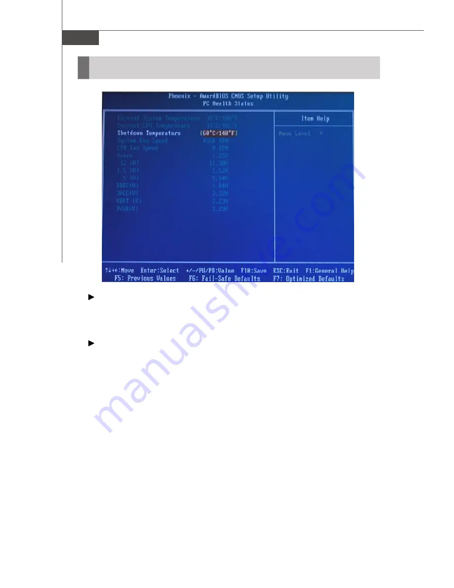
Current  System/CPU  Temperature,  System/CPU  Fan Speed,  Vcore

(V), 12(V), 1.5(V), 5(V), DDR2(V), 3VCC(V), VBAT(V),  3VSB(V)

These items display the current status of all of the monitored hardware devices/
components such as CPU voltages, temperatures and all fans

 speeds.

  Shutdown  Temperature

If the CPU temperature reaches the limit preset in this setting, the system will
shut  down automatically.

PC Health Status

Summary of Contents for AXIS 945GM - Axis - 945GM

Page 1: ...Axis 945GM Series MS 6417 V1 X Barebone G52 64171X1 ...

Page 2: ... to radio communications However there is no guarantee that interference will not occur in a particular installation If this equipment does cause harmful interference to radio or television reception which can be determined by turning the equipment off and on the user is encouraged to try to correct the interference by one or more of the measures listed below Reorient or relocate the receiving ant...

Page 3: ...ct incorporates copyright protection technology that is protected by U S patents and other intellectual property rights Use of this copyright protection technol ogy must be authorized by Macrovision and is intended for home and other limited viewing uses only unless otherwise authorized by Macrovision Reverse engineering or disassembly is prohibited Revision History Revision Revision History Date ...

Page 4: ...ngs on the equipment should be noted 10 Never pour any liquid into the opening that could damage or cause electrical shock 11 If any of the following situations arises get the equipment checked by service personnel The power cord or plug is damaged Liquid has penetrated into the equipment The equipment has been exposed to moisture The equipment does not work well or you can not get it work accordi...

Page 5: ...G 0 75mm2 2 Internal part is hazardous moving parts please keep fingers and other body parts away 3 For pluggable equipment the socket outlet shall be installed near the equipment and shall be easily accessible 4 Do not disable the protective earth pin from the plug the equipment must be connected to an earthed mains socket outlet ...

Page 6: ...vi WEEE Statement ...

Page 7: ...vii ...

Page 8: ...viii ...

Page 9: ...el 2 7 Audio Ports 2 7 USB Ports 2 7 Rear Panel 2 8 Connectors 2 10 IDE Connector IDE1 2 10 Serial ATAII Connectors SATA1 SATA2 2 10 Fan Power Connectors SYSFAN1 CPUFAN1 2 11 Front Panel Connector JFP1 2 11 Front Panel Audio Connector JAUD1 2 12 Front USB Connectors F_USB F_USB2 2 13 Floppy Disk Drive Connector FDD1 2 13 Jumper 2 14 Clear CMOS Jumper CLR_CMOS1 2 14 Slot 2 15 PCI Slot PCI1 For Rise...

Page 10: ...Drive 4 5 Removing Card Reader 4 6 Removing Riser Card 4 7 Removing Hard Disk Drive 4 7 Installing Hard Disk Drive 4 8 Installing Riser Card 4 8 Installing Card Reader 4 9 Installing Optical Disk Drive 4 9 Installing Memory Modules 4 11 Installing CPU 4 11 Installing CPU Cooler 4 13 Restoring Top Cover 4 14 Installing Footstand 4 15 Appendix A Realtek ALC655 Audio A 1 Installing the Audio Driver A...

Page 11: ...r purchasing Axis 945GM MS 6417 barebone Axis 945GM barebone is your best Slim PC choice With the fantastic appearance and ultra small form factor it can easily be set anywhere The fea ture packed platform also gives you an exciting PC experience ...

Page 12: ...ported FSB 667 533 MHz Chipset North Bridge Intel 945GM South Bridge Intel ICH7 MDH 82801GHM Memory Support DDRII 533 667 SDRAM 4GB Max 2 DDRII DIMMs 240pin 1 8V LAN Supports Dual Intel 10 100 1000 LAN by two Intel 82541PI Giga LAN controller Audio Chip integrated by Realtek ALC658 Flexible 5 1 channel audio Compliant with AC97 Spec IDE 1 IDE port by Intel ICH7 MDH Supports Ultra DMA 66 100 mode S...

Page 13: ...Line In 1 Line Out 1 Mic In 1 D Sub VGA port 1 DVI port Front Panel 2 audio jacks Mic In x 1 Headphone Out x 1 2 USB 2 0 ports On Board Pinheaders 1 CD In 2 USB 2 0 pinheaders 1 front panel pinheader 1 front audio connector Slots 1 PCI v2 3 slot for standard PCI add on card Form Factor Mini ITX form factor size 170mm x 170mm Mounting 4 mounting holes ...

Page 14: ... 1 4 1 Mic In pink 6 Optical Drive Eject Close Button 2 Headphone Out green 7 Card Reader Drive optional 3 USB 2 0 ports x 2 8 Optical Drive optional 4 Power Button 9 Power LED 5 HDD LED System Configuration Front View ...

Page 15: ...ed Rear View 1 PS 2 Keyboard purple 8 Line Out green 2 PS 2 Mouse green 9 Line In blue 3 VGA Port 10 Power Jack 4 DVI Port 11 Ventilation Hole 5 Serial Ports 12 Expansion Slots 6 USB 2 0 Ports 13 LAN Jacks 7 Mic In pink ...

Page 16: ...mension 363mm D x 300mm W x 72mm H Minimized screw structure Detachable bay housing Multiple ventilation holes 1 System Ventilation Hole 3 CPU Fan Ventilation Hole 2 Power Supply Ventilation Hole 4 System Ventilation Hole Bottom Side Back ...

Page 17: ... cooling effects The specially designed CPU cooler supports Intel Yonah Core Duo T2000 Sequence and Merom Core 2 Duo T5000 and T7000 Sequence Processors The follwing figures illustrate how the system fan effectively ex hausts hot air through multiple ventilation holes Thermal Solution CPU Fan Picture Hot Air Out Air Flow Direction Thermal Solution ...

Page 18: ...MS 6417 Barebone 1 8 System Picture Front Panel Ventilation Hole System Fan Power Supply Ventilation Hole Ventilation Hole Power Supply Fan ...

Page 19: ...mpleted please keep other objects away from the ventilationholeat least 2 5cm andabove Do not block the ventilation hole System Air Flow Direction Front Panel Ventilation Hole System Fan Power Supply Fan Power Supply Ventilation Hole Ventilation Hole ...

Page 20: ...the installation procedures For some components if you install in the wrong orientation the components will not work properly Use a grounded wrist strap before handling com puter components Static electricity may damage the components Chapter 2 Hardware Setup Always unplug the power cord before in serting any add on card or module ONLY FOR SERVICE PERSONEL ...

Page 21: ... 945GM LAN Chip 82541P1 Intel 82541P1 F_USB1 ATX1 SATA2 SATA1 F_USB2 DIMM1 SYSFAN1 CPUFAN1 DIMM2 FDD1 JFP1 IDE1 CLR_CMOS1 JPW1 Top mouse Bottom keyboard Top DVI Port Bottom VGA Port Top COM1 Bottom COM2 Top LAN Jack Bottom USB ports Top LAN Jack Bottom USB ports T Line In M Line Out B Mic In ALC658 Realtek ...

Page 22: ... easy CPU installation When you are installing the CPU make sure the CPU has a heat sink and a cooling fan attached on the top to prevent overheating For the latest informa tion about CPU please visit http www msi com tw program products slim_pc slm pro_slm_cpu_support php Important Overheating will seriously damage the CPU and system al ways make sure the cooling fan can work properly to protect ...

Page 23: ...t DIMM1 DIMM2 Otherwise you are not able to boot up your system and your mainboard might be damaged Memory Installing DDRII Modules 1 The DDRII DIMM has only one notch on the center of module The Module will only fit in the right orientation 2 Insert the DIMM memory module vertically into the DIMM slot Then push it in until the golden finger on the memory module is deeply inserted in the socket 3 ...

Page 24: ...e power supply firmly into the connector Power Supply Important 1 Make sure that all the connectors are connected to proper ATX power supplies to ensure stable operation of the mainboard 2 Power supply of 130 watts and above is highly recommended for system stability 3 ATX 12V power connection should be greater than 6A ATX 12V Power Connector JPW1 This 12V power connector is used to provide power ...

Page 25: ...al Host Controller Interface Universal Serial Bus root for attaching USB devices such as keyboard mouse or other USB compatible devices You can plug the USB devices directly into these connectors Front Panel The Front Panel provides the following connectors USB Ports Headphone Out green Mic In pink USB Ports Headphone Out green Mic In pink ...

Page 26: ...onitor cable into the DVI connector and make sure that the other end of the cable is properly con nected to your monitor refer to your monitor manual for more information Serial Ports The mainboard offers two 9 pins male DIN connectors as serial ports The ports are 16550A high speed communication ports that send receive 16 bytes FIFOs You can attach a serial mouse or other serial devices directly ...

Page 27: ... headphones Pink audio jack Mic In Center LEF is a connector for microphones LAN RJ 45 Jacks The standard RJ 45 jacks are for connection to single Local Area Network LAN You can connect a network cable to it Link Indicator Activity Indicator Left Condition Off On steadystate On brighter pulsing On On Orange Orange Green Right LAN linkis not established LAN linkis established Thecomputeriscommunica...

Page 28: ...lows you to connect to the IDE devices HDD CD ROM Connectors IDE1 Serial ATAII Connectors SATA1 SATA2 SATA1 SATA2 are dual high speed Serial ATAII interface ports Each supports data rates of 300MB s All connectors are fully compliant with Serial ATA specification Each Serial ATA connector can connect to 1 hard disk device SATA1 SATA2 1 3 5 7 Pin Definition PIN SIGNAL PIN SIGNAL 2 4 6 GND TXN RXN G...

Page 29: ...o GND PowerSwitchhigh reference pull up Reset Switch high reference pull up PowerSwitch lowreferencepull down to GND Reserved Donot use Important Always consult the vendors for proper CPU cooling fan Fan Power Connectors SYSFAN1 CPUFAN1 The Fan Power Connectors support system cooling fan with 12V It supports 3 pins head connector When connecting the wire to the connectors always take note that the...

Page 30: ...PTION N C Ground usedbyanalog audio circuits Microphonepower Filtered 5V used by analog audio circuits Right channel audio signal to front panel Right channel audio signal return from front panel N C No pin Left channelaudio signal to frontpanel Left channel audio signal return from front panel JAUD1 9 10 Important If you don t want to connect to the front audio header pins 5 6 9 10 have to be jum...

Page 31: ...ncreases data transfer rate up to a maximum throughput of 480Mbps which is 40 times faster than USB 1 1 and is ideal for connecting high speed USB interface peripherals such as USB HDD digital cameras MP3 players printers modems and the like VCC USB0 USB0 GND Key no pin Pin Definition 2 4 6 8 10 PIN SIGNAL PIN SIGNAL 1 3 5 7 9 VCC USB1 USB1 GND USBOC F_USB1 F_USB2 9 10 1 2 Important Note that the ...

Page 32: ...battery to keep the system configuration data With the CMOS RAM the system can automatically boot OS every time it is turned on If you want to clear the system configuration use the CLR_CMOS Clear CMOS Jumper to clear data Follow the instructions below to clear the data Jumper Keep Data 1 3 3 1 Clear Data Important You can clear CMOS by shorting 2 3 pin while the system is off Then return to 1 2 p...

Page 33: ... included in the barebone The Riser Card allows you to insert one PCI expansion card You can insert any type of PCI card to meet your needs When adding or removing expansion card make sure that you unplug the power supply first Meanwhile read the documentation for the expansion card to make any necessary hardware or software settings Slot PCI Slot Riser Card ...

Page 34: ...e BIOS Setup program and allows you to configure the system for optimum use You may need to run the Setup program when An error message appears on the screen during the system booting up and requests you to run SETUP You want to change the default settings for custom ized features ...

Page 35: ...e items under each BIOS category described in this chapter are under continuous update for better system performance Therefore the description may be slightly dif ferent from the latest BIOS and should be held for reference only 2 Upon boot up the 1st line appearing after the memory count is the BIOS version It is usually in the format W7265IMS V1 0 060715 where 1st digit refers to BIOS maker as A...

Page 36: ...en you can use the control keys to enter values and move from field to field within a sub menu If you want to return to the main menu just press the Esc General Help F1 The BIOS setup program provides a General Help screen You can call up this screen from any menu by simply pressing F1 The Help screen lists the appropriate keys to use and the possible selections for the highlighted item Press Esc ...

Page 37: ...atures Use this menu to change the values in the chipset registers and optimize your system s performance Integrated Peripherals Use this menu to specify your settings for integrated peripherals Power Management Setup Use this menu to specify your settings for power management PnP PCI Configurations This entry appears if your system supports PnP PCI PC Health Status This entry shows your PC health...

Page 38: ...stable system performance Load Optimized Defaults Use this menu to load the default values set by the mainboard manufacturer specifically for optimal performance of the mainboard Set Supervisor Password Use this menu to set Supervisor Password Set User Password Use this menu to set User Password Save Exit Setup Save changes to CMOS and exit setup Exit Without Saving Abandon all changes and exit se...

Page 39: ...ay Day of the week from Sun to Sat determined by BIOS Read only Month The month from Jan through Dec Date The date from 1 to 31 can be keyed by numeric function keys Year The year can be adjusted by users Time hh mm ss This allows you to set the system time that you want usually the current time The time format is hour minute second Standard CMOS Features ...

Page 40: ...formation is asked to be entered to the following items Enter the information directly from the keyboard This information should be provided in the documentation from your hard disk vendor or the system manufacturer Access Mode The settings are CHS LBA Large Auto Capacity The formatted size of the storage device Cylinder Number of cylinders Head Number of heads Precomp Write precompensation Landin...

Page 41: ...tem shows the BIOS version of your system read only CPU Type CPU ID uCode ID CPU Frequency CPU L2 Cache The three items show the CPU related information of your system read only System Information Press Enter to for the sub menu of each item ...

Page 42: ...rning message on screen and beep CPU L3 Cache Level 3 cache is the extra cache built into motherboards between the micro processor and the main memory Located away from the CPU the L3 cache is slower than the L1 L2 caches This setting allows you to turn on or off the L3 cache Hard Disk Boot Priority Press Enter to enter a sub menu which shows every current hard drive installed Use PageUp or PageDo...

Page 43: ...tion This specifies the type of BIOS password protection that is implemented Settings are described below Setup The password prompt appears only when end users try to run Setup System A password prompt appears every time when the computer is powered on or when end users try to run Setup APIC Mode This field is used to enable or disable the APIC Advanced Programmable Interrupt Controller Due to com...

Page 44: ...buffer size increases video performance DVMT Mode Use the field to select the mode of the digital monitor you use Setting options Fixed Mode DVMT Mode Both DVMT FIXED Memory Size Specify the size of DVMT memory to allocate for video memory Boot Display Use the field to select the type of device you want to use as the display s of the system Important Do not change these settings unless you are fam...

Page 45: ...ed by BIOS and you will be able to see the IDE Device status listed in Standard COMS Features Legacy Mode PATA and SATA will be combined Max of 2 IDE drives in each channel are available Native Mode PATA and SATA will both be enabled Max of 6 IDE drives are supported SATA PORT Speed Settings This setting controls the speed of the SATA port OnChip IDE Device Press Enter and the following sub menu a...

Page 46: ...nd you have a USB keyboard AC97 Audio Auto allows the mainboard to detect whether an audio device is used If an audio device is detected the onboard AC97 Audio Codec 97 controller will be enabled if not it is disabled Disable the controller if you want to use other controller cards to connect an audio device Onboard LAN Device 1 2 This setting controls the onboard LAN 1 2 device Onboard Lan 1 2 Bo...

Page 47: ...or the system has no floppy drive select Disabled in this field Onboard Serial Port 1 2 These items specify the base I O port addresses of the onboard Serial Port 1 Serial Port 2 Selecting Auto allows AMIBIOS to automatically determine the correct base I O port address Settings 3F8 IRQ4 2F8 IRQ3 3E8 IRQ4 2E8 IRQ3 and Disabled SuperIO Device Press Enter and the following sub menu appears ...

Page 48: ...tions are S1 POS The S1 sleep mode is a low power state In this state no system context is lost CPU or chipset and hardware main tains all system context S3 STR The S3 sleep mode is a lower power state where the infor mation of system configuration and open applications files is saved to main memory that remains powered while most other hardware components turn off to save energy The information s...

Page 49: ...Up From S3 S4 When setting to Enabled this setting allows your system to be awakened from S3 state Resume by Alarm When Enabled your can set the date and time at which the RTC real time clock alarm awakens the system from suspend mode POWER ON Function This controls how the PS 2 mouse or keyboard can power on the system PWRON After PWR fail This item specifies whether your system will reboot after...

Page 50: ...ations Init Display First This setting specifies which VGA card is your primary graphics adapter Set ting options are PCI Slot The system initializes the PCI graphic card first Onboard The system initializes the VGA graphic card first ...

Page 51: ...VCC V VBAT V 3VSB V These items display the current status of all of the monitored hardware devices components such as CPU voltages temperatures and all fans speeds Shutdown Temperature If the CPU temperature reaches the limit preset in this setting the system will shut down automatically PC Health Status ...

Page 52: ...hat the spikes of the pulses are reduced to flatter curves Important Important 1 If you do not have any EMI problem leave the setting at Disabled for optimal system stability and performance But if you are plagued by EMI select the value of Spread Spectrum for EMI reduction 2 The greater the Spread Spectrum value is the greater the EMI is reduced and the system will become less stable For the most...

Page 53: ...lt values set by the mainboard manufacturer specifically for optimal performance of the mainboard The Fail Safe Defaults are the default values set by the BIOS vendor for stable system performance When you select Load Fail Safe Defaults a message as below appears Load Fail Safe Optimized Defaults Pressing Y loads the BIOS default values for the most stable minimal system performance ...

Page 54: ...a set password just press Enter when you are prompted to enter the password A message will show up confirming the password will be disabled Once the password is disabled the system will boot and you can enter Setup without entering any password When a password has been set you will be prompted to enter it every time you try to enter Setup This prevents an unauthorized person from changing any part...

Page 55: ...cedures While doing the installation be careful in holding the components and follow the installation procedures Use a grounded wrist strap before handling computer components Static electricity may damage the components Always unplug the power cord before in serting any add on card or module ONLY FOR SERVICE PERSONEL ...

Page 56: ...all CPU CPU Cooler Memory Modules Riser Card Card Reader Hard Disk Drive and Optical Disk Drive Installation Tools Screws Two types of screws are used in assembling the barebone Screw type 1 M3XL4 Screw type 2 6 32 Screwdriver Gloves Overview Screw type 1 M3XL4 This screw is used to lock the Top Cover Card Reader Riser Bracket FDD and ODD Screw type 2 6 32 This screw is used to lock the Power Supp...

Page 57: ...ck the items listed below for basic system operation The Footstand and the CPU cooler are included in the package other items are optional Footstand IDE or SATA HDD Optional Card Reader Optional CPU Cooler Optical Drive Optional DDRII SDRAM Optional Riser Card Mobile CPU Optional ...

Page 58: ...move the Top Cover from the system with hands 1 Removing Top Cover Installation Procedures Remove the Front Panel from the system with hands to release all the cages Important Be careful with the three hooks on the Front Panel Remember to remove them gently with hands or the damages can be made easily ...

Page 59: ...4 5 System Assembly 2 Removing Optical Disk Drive ODD Disconnect the cable and the power cord of the ODD Optional Pull the Lock Bracket to release the ODD Remove the ODD from the system This direction ...

Page 60: ...lock the four screws to release the Card Reader Press Press Important 3 Removing Card Reader Disconnect the cable of Card Reader Optional This multi function Card Reader tray is designed to be a 3 in 1 device with three different choices for installtion which includes the Card Reader itself HDD and FDD ...

Page 61: ...e the HDD tray from the sys tem with hands Unlock the screw from the chassis with screwdriver Remove the Riser Card Support Bracket from the system with hands Lift up Lift up 4 Removing Riser Card 5 Removing Hard Disk Drvie HDD ...

Page 62: ...hands Lock the screw to the chassis with screwdrive Install the Riser Card Support Bracket to the system with hands Put down 6 Installing Hard Disk Drvie HDD 7 Installing Riser Card Insert the HDD Optional into theHDD tray and lock the four screws Put down Insert ...

Page 63: ...cket Remember to lock the four screws to fix the Card Reader before inserting Insert the ODD into the system Important Please note that the length of the ODD should be under 185MM Press Press Connect the cable of Card Reader Optional 8 Installing Card Reader 9 Installing Optical Disk Drive ODD ...

Page 64: ...MS 6417 Barebone 4 10 Find the location of DIMM slots 10 Installing Memory Modules Push the Lock Bracket to fix the ODD Connect the cable and the power cord of the ODD Optional This direction ...

Page 65: ... Assembly Insert the Memory Modules vertically into the DIMM slots Loose the screw on the CPU socket with a screwdriver in anticlockwise direction 11 Installing CPU Find the location of CPU Put down Anticlockwise ...

Page 66: ...U on top of the socket Make sure to align the gold arrow on the CPU with the arrow key on the socket Lock the screw on the CPU socket with a screwdriver in clockwise direction Arrow here Clockwise Important Important On the front end of the CPU socket is a locking mechanism designed into the form of a screw Make sure that you actuate or deactuate this mechanism with a screwdriver before and after ...

Page 67: ...ock the four screws Do not fix any screw until all the four screws are in the position and lock the four screws with balance or it may shift the CPU position to cause the system unbootable Remove the sticker before installing Connect the cable of CPU Fan 12 Installing CPU Cooler ...

Page 68: ...bone 4 14 13 Restoring Top Cover Important Follow the steps to restore the Top Cover to the system with hands Lock the two screws on the Back Panel with screwdriver Restore the Front Panel to the sys tem with hands ...

Page 69: ...Assembly Horizontal Type Tower Type 5 Installing Footstand Move the system until its bottom part fit against the end of the footstand Place the footstand on the table Lift up the system and put it on the footstand ...

Page 70: ...ALC658 chip which provides support for 6 channel audio output including 2 Front 2 Rear 1 Center and 1 Subwoofer channel ALC658 allows the board to attach 4 or 6 speakers for better surround sound effect The section will tell you how to install and use the 2 4 6 channel audio function on the board ...

Page 71: ... The following illustrations are based on Windows XP environment and could look slightly different if you install the drivers in different operating systems Installing the Audio Driver Important The AC97 Audio Configuration software utility is under continuous update to enhance audio applications Hence the program screens shown here in this appendix may be slightly different from the latest softwa...

Page 72: ...A 3 Realtek ALC658 Audio 3 Click Next to install the AC97 Audio software 4 Click Finish to restart the system Click here Click here Select this ...

Page 73: ...tray at the lower right corner of the screen to activate the AC97 Audio Configuration Sound Effect Here you can select a sound effect you like from the Environment list You may also edit the properties for an environment as you wish by clicking the Edit button then just scroll the bar in the bottom for each property to adjust Software Configuration ...

Page 74: ...unction which will automatically remove human voice lyrics and leave melody for you to sing the song Note that this function applies only for 2 channel audio operation Just check the Voice Cancellation box and then click OK to activate the Karaoke function ...

Page 75: ...al sound sources You may choose the provided sound effects and the equalizer will adjust automatically If you like you may also load an equalizer setting or make an new equalizer setting to save as an new one by using the buttons Load and Save Or you may click Reset to use the default value ...

Page 76: ... audio function and speakers 2 1 1 Select a desired multi channel operation from Number of Speakers a N CHeadphone for the common headphone b 2 Channel Mode for Stereo Speaker Output c 4 Channel Mode for 4 Speaker Output d 6 Channel Mode for 5 1 Speaker Output 2 Then click OK to apply the configuration ...

Page 77: ...ly If any speaker fails to make sound then check whether the cable is inserted firmly to the connector or replace the bad speakers with good ones Select the speaker by clicking it to test its functionality The one you select will light up and make testing sound Subwoofer Front Right Center Front Left Select this function Rear Left Rear Right ...

Page 78: ... window 2 While you are testing the speakers in 6 Channel Mode if the sound coming from the center speaker and subwoofer is swapped you should select Swap Center Subwoofer Output to readjust these two channels HRTF Demo In this tab you may adjust your HRTF Head Related Transfer Functions 3D positional audio before playing 3D audio applications like gaming You may also select different environment ...

Page 79: ...s tab it provides some information about the AC97 Audio Configura tion utility including Audio Driver Version DirectX Version Audio Controller AC97 Codec You may also select the language of this utility by choosing from the Language list ...

Page 80: ...utility and have your speakers correctly connected to the Back Panel Connecting the Speakers When you have set the Multi Channel Audio Function mode properly in the software utility connect your speakers to the correct phone jacks in accordance with the setting in software configuration 2 Channel Mode for Stereo Speaker Output Refer to the following diagram and caption for the function of each pho...

Page 81: ...r 4 Speaker Output The audio jacks on the back panel always provide 2 channel analog audio output function however these audio jacks can be transformed to 4 or 6 channel analog audio jacks by selecting the corresponding multi channel operation from No of Speakers Refer to the following diagram and caption for the founction of each jack on the back panel when 4 Channel Mode is selected Back Panel 2...

Page 82: ...ker Output is selected n 6 Channel Mode for 6 Speaker Output Refer to the following diagram and caption for the function of each jack on the back panel when 6 Channel Mode is selected Back Panel 2 3 1 Important While you are testing the speakers in 6 Channel Mode if the sound coming from the center speaker and subwoofer is swapped you should select Swap Center Subwoofer Output to readjust these tw...

Reviews: