4. MEASURING PROCEDURE
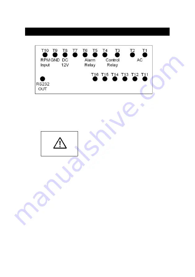
Terminal layout
Fig. 2
4-1 Terminal connection
1)Input the ACV power ( 90 to 260 ACV ) to T1, T2.
Do not input the
over voltage to the
AC input terminals.
2)Connect the " Control Relay " output from T3, T4.
Connect the " Alarm Relay " output from T5, T6.
3)Connect the following optional sensor ( or similar sensor ).
* Proximity sensor, PX-01.
* Photo sensor, PI-06.
to the input terminal T8, T9, T10.
T8 is DC 12 V power supply terminal.
T9 is the ground ( - ) terminal.
T10 is the pulse input terminal.
5


