


CA4HC WALK-BEHIND TROWEL • OPERATION MANUAL — REV. #1 (06/24/20) — PAGE 25
INSPECTION
BEFORE STARTING
1. Clean the trowel, particularly the engine cooling air
inlet. Remove all dirt and dust.
2. Inspect the engine air cleaner for dirt and dust. Replace
the air cleaner if it is dirty.
3. Inspect the carburetor for external dirt and dust. Clean
with dry compressed air as needed.
4. Inspect all fastening nuts and bolts for tightness.
ENGINE OIL
1. Place the trowel on secure, level ground with the
engine
OFF
.
2. Remove the dipstick (Figure 14) from the engine oil
filler hole and wipe it clean.
Figure 14. Engine Oil Dipstick
3. Reinsert the dipstick, then remove it again without
screwing it into the filler neck. Check the oil level shown
on the dipstick.
4. If the oil level is low (Figure 15), fill to the edge of the
oil filler hole with the recommended oil type listed
in Table 5. Refer to Table 2 for maximum engine oil
capacity.
Figure 15. Engine Oil Level
DIPSTICK
UPPER LIMIT
LOWER LIMIT
Table 5. Engine Oil Type
Season
Temperature
Oil Type
Summer
25°C or Higher
SAE 10W-30
Spring/Fall
25°C–10°C
SAE 10W-30/20
Winter
0°C or Lower
SAE 10W-10
FUEL
Remove the fuel filler cap and inspect the fuel level in
the tank. If fuel is low, replenish with 86 octane or higher
unleaded gasoline.
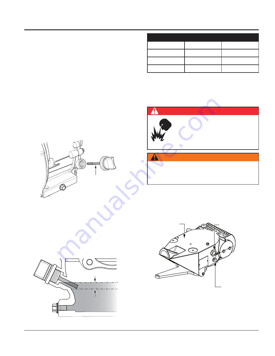
GEARBOX OIL
1. Look at the sight glass on the side of the gearbox
(Figure 16) to determine if gearbox oil is low. The
correct oil level is to the halfway point on the sight glass.
Figure 16. Gearbox Oil
DANGER
Motor fuels are
highly flammable
and can be dangerous if mishandled.
DO NOT
smoke while refueling.
DO NOT
attempt to refuel while the engine is
running
or
hot
!
WARNING
ALWAYS
use a strainer for filtration while refueling.
NEVER
top off fuel.
ALWAYS
wipe up any spilled fuel
immediately.
SIGHT GLASS
DRAIN/FILL
PLUG
GEARBOX
To
go
to
Discount-Equipment.com


