MQ Multiquip Mikasa MVH120 Service Manual Download Page 5

2. INSPECTION PROCEDURE

1. External appearance check

(1) Installation of parts (loosened screw, defective parts, etc.) 
(2) Damage on machine 
(3) Oil check (level and contamination) 

a. Engine oil (SAE10W-30 when shipped) (See Table 1 for the capacity)
b. Vibrator
c. Hydraulic oil (Traveling)

(4) V-belt for proper tension, damage, crack, hardening, etc. 
(5) Isolation rubber for damage, crack, fatigue, hardening, etc. 

2. Operating test

(1) Engine   

Engine speed check (Max. set rpm and idling) 

(2) Traveling   

a. Check selection of forward/reverse travel.
b. Check speed of forward/reverse travel.

(3) Check for abnormal noise during operation. 
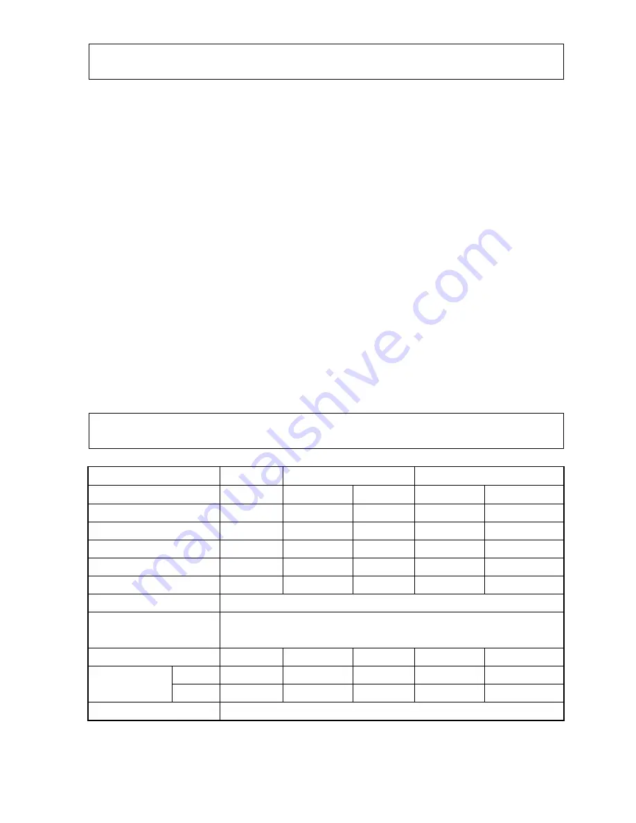
Table 1 

3.Engine, Oil and V-belt

Type

MVH-R60

MVH-120

MVH-150

Mounted engine 

HondaGX120

HondaGX160

RobinEH17

HondaGX200 RobinDY23(DS)

Set rpm (min

-1

3600 3600  3600 3600 

3200 

Fuel tank capacity (Liter) 

2.5

3.6

3.6

3.6

3.2

Fuel consumption (L/h) 

0.95

1.1

1.1

1.2

1.0

Engine oil capacity (L) 

0.6

0.6

0.65

0.6

0.9

Vibrator oil capacity (L) 

0.25

0.35

0.65 0.35 

0.35 

Lubrication oil in use 

Engine Oil SAE10W-30 

Vibrator oil replacement 

interval (hours) 

200 

Size and quantity of belt 

RPF3320X1

RPF3320X1 PRF3320X1

RPF3350X1 

RPF3340X1 

Forward 

0

25 0

23 0

23 0

25

0

25 

Compaction 

speed (m/min)    Reverse 

0

25 0

21 0

21 0

25

0

25 

Hydraulic oil 

Shell Stella #46 or equivalent 

Summary of Contents for Mikasa MVH120

Page 1: ...SERVICE M MA AN NU UA AL L M MV VH H6 60 0 1 12 20 0 1 15 50 0 P PL LA AT TE E C CO OM MP PA AC CT TO OR RS S MAINTENANCE DISASSEMBLY DIAGRAMS TROUBLESHOOTING Manual No MVH60120150SM Updated 3 30 15 ...

Page 2: ...cause cancer birth defects and other reproductive harm Some examples of these chemicals are Lead and lead based paint Crystalline silica from bricks Cement and other masonry products Arsenic and chromium from chemically treated lumber Your risk from these exposures varies depending on how often you do this type of work To reduce your exposure to these chemicals ALWAYS work in a well ventilated are...

Page 3: ...es for Conducting Service 3 5 Disassembly and Reassembly 4 1 Operation System 4 2 Basic Macine 8 3 Vibration System 9 4 Hand Pump System 19 6 Periodical Inspection and Maintenance Work 21 7 Trouble Shooting 26 8 Wiring Diagram 29 All information for MVH 60 120 150 is provided by Manufacture ...

Page 4: ...Adjustable wrench 2 Hexagonal wrench 3 16inch 5mm 8mm 10mm 14mm 3 Plier 4 External snap ring plier Internal snap ring plier bent type also use 5 Screwdriver flat and cross 6 Metal and plastic hammers 7 Pulley puller 8 Sealing compound Locktite 242 271 and 638 9 Liquid gasket 10 Press tool 1 ...

Page 5: ... of forward reverse travel 3 Check for abnormal noise during operation Table 1 3 Engine Oil and V belt Type MVH R60 MVH 120 MVH 150 Mounted engine HondaGX120 HondaGX160 RobinEH17 HondaGX200 RobinDY23 DS Set rpm min 1 3600 3600 3600 3600 3200 Fuel tank capacity Liter 2 5 3 6 3 6 3 6 3 2 Fuel consumption L h 0 95 1 1 1 1 1 2 1 0 Engine oil capacity L 0 6 0 6 0 65 0 6 0 9 Vibrator oil capacity L 0 25...

Page 6: ...Before coating with Loctite clean the screws thoroughly Note All the screws in use with this machine are right handed Table of Tightening Torque kgf cm Table 2 Screw diameter Material 6mm 8mm 10mm 12mm 14mm 16mm 18mm 20mm 4T SS41 70 150 300 500 750 1 100 1 400 2 000 6 8T S45C 100 250 500 800 1 300 2 000 2 700 3 800 11T SCM3 150 400 800 1 200 2 000 2 900 4 200 5 600 In case counter part is made fro...

Page 7: ...ile observing below 1 For installing the handle assembly 1 to the base first have the four bolts 28 tightened only lightly which are fixing the handle bracket R and L 26 27 in the developed drawing and after adjusting resistance in handle operation by means of double nut 12 retighten them securely 2 Have the throttle lever resistance adjusted with double nut 46 47 before fixing the throttle lever ...

Page 8: ... required Reassembling Procedure 1 Insert the slider 53 into throttle body 51 with its groove coming in the back Photo D 2 Install the outer governor wire 64 Photo E In case the end of inner governor wire should be bent install inner and outer wires together by taking measures of steps 3 and 4 below to get the result as shown in Photo H 3 Insert inner part of governor wire 64 through throttle body...

Page 9: ...ottle body 51 P Plain washers s hoto L and M Throttle body 51 Belleville spring 58 x 2 Plain washer M10 57 Throttle lever 54 Plain washer M10 57 Nut M10 61 Cap nut M10 60 hould be installed facing each T ss of throttle lever should be adjusted Tu in the hollow setscrew 59 to lock the throttle fter assembling throttle lever stops when it reaches other ightne with nut M10 and cap nut M10 To increase...

Page 10: ...the base Note After removing hydraulic hose apply blind plug to prevent any dust from entering Removing hose clamp 20 its mounting bolt 21 hand pump locking nut 18 and two stud bolts pump 16 allows to remove the hand pump 11 from handle 1 Reassembly Reassembly should be conducted with the disassembling procedure reversed while observing below 1 For installing the handle assembly 1 to the base firs...

Page 11: ... four bolts which have been fixing isolation rubber to the base 1 lift the base assembly upward The compaction plate assembly will be separated Reassembly Reassembly should be conducted with the disassembly procedures reversed while observing below 1 Coat the bolts and nuts for mounting the isolation rubber with Loctite 242 2 All the mounting bolts for the basic machine should be coated with Locti...

Page 12: ...lts 30 removed remove cylinder 29 4 Disassembling the piston 4 1 With the vibrator case inverted upside down rotate gear in either direction to cause the piston assembly 15 to be projected from the vibrator case before removing the expansion stop ring 17 from inside of the piston Use a bent nose type stop ring plier for this purpose See Fig 2 Fig 2 Piston Piston Expansion stop ring Gear 4 2 Withdr...

Page 13: ...10 ...

Page 14: ...Fig 7 MVH 120 AND 150 4 4 Remove seal cap 25 4 5 Remove pendulum 18 from each pendulum shaft See Fig 8 4 6 With the driven shaft assembly pushed out to the side opposite to pulley and the bearing 2 taken out remove the driven shaft assembly from the vibrator case See Fig 8 4 7 Disassembling the driven shaft Remove four mounting bolts 10 and take out bearing holder 8 See Fig 9 4 8 Remove four mount...

Page 15: ...t with respect to bearing 2 pendulum 18 hex socket head bolt 19 pendulum pulley 35 washer 37 mounting bolt 38 belt cover lower 45 and mounting socket head bolt 46 2 For MVH 150 three different types of pendulum pulleys 35 are available according to engine model 12 ...

Page 16: ...d remove pendulum 18 and push out the drive shaft assembly to the bearing cover side before removing the bearing See Fig 12 5 4 As shown in Fig 13 remove upper stop ring 5 and engage supports between the drive gear 30 and inner surface of vibrator case Press the drive shaft from top and remove drive gear within the vibrator case The gear having been pressed in over the distance of about 2cm its re...

Page 17: ...ar 7 into drive shaft 3 with its punched side coming to top Opposite to belt side See Fig 15 2 1 Vibrator case is to be supported by means of Jig B with its belt side coming to bottom 2 2 Have the key 10x8x19 6 and upper opposite to belt side stop ring 5 engaged to drive shaft After placing such assembly inside the vibrator case have the drive gear 7 with its punched side coming to top and stop ri...

Page 18: ...y attention o direction t of flange face Fig 19 Driven shaft Driven shaft side Apply molybdenum grease Fig 20 3 Insert piston rod 11 to the driven shaft See Fig 20 4 Press the parallel pin 12 via cam ring into piston rod After pressing it in make sure that the parallel pin does not protrude from periphery of the cam ring See Fig 21 5 After inserting driven shaft gear 31 to cam ring 7 lock it with ...

Page 19: ...180kgf cm 180kgf cm Apply Locktite 271 Tightening torque Fig 25 Fig 26 Driven shaft assembl Drive gear 30 Driven gear 31 Mating punch marks Fig 27 Piston rod Knock pin Bearing Gear Pulley side Pulley side Driven shaft Align Fig 28 Note When inserting driven gear to driven shaft make sure to align the punch mark of gear with pendulum installing position of pendulum shaft before placing the knock pi...

Page 20: ...rted Fig 30 USH packing 2 Install USH packing to piston See Fig 30 Push it in with your finger after coating with oil Make certain that piston has no scar or scratch Use care not to damage piston Install packing in proper direction 3 Place the piston over the bearing and push the assembly into vibrator case before retaining it with the expansion stop ring which had been installed earlier See Fig 3...

Page 21: ...ee Bond 1215 or equivalent to the thickness of about 0 5mm 3 That completes the reassembly of vibrator but make certain that it rotates smoothly by turning its pendulum shaft drive shaft manually If resistance is great tapping on the gear side with plastic hammer lightly will help the rotation to be smooth Do not possibly tap on the gear tooth 4 Install the vibrator assembly to compaction plate Th...

Page 22: ...the pump Remove four hex socket head bolts 21 20 2 3 With blank plug 23 17 removed take off the stopper 22 16 2 4 With spring retainer 18 or hose joint 19 removed take off the spring 16 17 14 2 5 With spring pin 6x25 20 13 removed take off control shaft 8 7 and cam A 2 6 Remove bush 9 8 2 7 With stop plug 19 18 removed from the bottom of pump body 1 take off the piston 4 from the pump body 1 2 8 I...

Page 23: ...r on vibrator side 5 3 With breather bolt at the cylinder top loosened remove cover 2 and fill the hose and cylinder with oil 46 Hydraulic oil Tighten the bolts after venting air 5 4 With the handle erected fill the hand pump assembly with appropriate amount of oil before reinstalling the cover 2 5 5 After conducting test run vent air again and check the oil tank of hand pump assembly for proper l...

Page 24: ...ngine Inspection See Engine Instruction Manual for detail Item Hours of Operation Oil and or fuel leakage Every 8 hours Daily Tightness of fasteners Every 8 hours Daily Engine oil Check and replenishment Engine oil Check and replenishment Replenish to specified level when insufficient Engine oil Replacement At first 20 hours every 100 hour thereafter Air cleaner Clean Every 50 hours Note Above int...

Page 25: ...otate the offset wrench clockwise until the belt is installed V belt reinstallation Note There is a risk for injury Use sufficient care for your hand not to be caught between the belt and clutch Use glove for protection c Checking the clutch Check the clutch simultaneously when you check V belt With the belt cover removed visually check the outer drum of clutch for seizure V groove for wear or dam...

Page 26: ... range of oil Lubrication oil to use Engine oil 10W 30 Oil Capacities R60 Series 0 25 Liter 120 Series 0 35 L 150 Series 0 35 L Note To prevent dust from entering clean the port before proceeding with the vibrator oil check Note In case any leakage from vibrator should be detected check vibrator oil frequently 6 Checking the hydraulic oil See Fig 36 a Check the hydraulic oil in every 100 hours of ...

Page 27: ...o OIL LEVEL Note ulic oil exactly to the OIL LEVEL Excessive filling causes oil to gush out of the breather Hydraulic oil to use Shell Tellus Oil 46 or its equivalent Fig 37 Vibrator Breather plug Hydraulic hose e careful not to allow any dust to enter t With the plug cap taken off the hand pump remove breather plug with 24mm wrench before disconnecting hydraulic hose which has entered vibrator cy...

Page 28: ...inal and connect terminal lastly Note When removing cables use care not to allow short circuiting between and terminals 3 Take out the battery from the machine b Checking and cleaning the battery 1 Check the battery for crack or any other damage 2 Check the terminals for decay If decayed polish it with wire brush or emery paper before coating the terminals with grease 3 Clean the externals of batt...

Page 29: ...f cylinder head or spark plugs defective Suction or exhaust valve stuck or Aeration in the piping Fuel filter clogged Tank cap breather hole clogged Fuel cock opening deficient Fuel not available in fuel tank Fuel not available at carburetor 2 Operation deficient Weak in power Compression normal and no misfiring Oil level in carburetor improper Air cleaner dirty Carbon deposited in cylinder Compre...

Page 30: ...stuck Fuel injection not available in combustion chamber Fuel not available in the tank Water or dust entered C Does not start even combustion and compression are normal Aeration in piping Engine oil viscosity too high or highly contaminated Improper starting procedure Does not reach starting rpm D Poor Battery 2 Insufficient output and deficient operation Compression insufficient See Due to defic...

Page 31: ... THE WHOLE Aeration in traveling hydraulic oil Internal defect in vibrator Excessive oil in vibrator Clutch slips V belt slips speed range Engine power output I nsufficient or rpm setting improper for Travel speed slow and vibration weak Connecting groove between gear pump input shaft and adapter broken or worn Selector valve clogged with dust Piston bearing broken in cylinder leakage in USH packi...

Page 32: ... not available Continuity available Continuity not available B Continuity not available Continuity available Continuity not available C Continuity not available Continuity not available Continuity not available Connect black terminal of the tester D Continuity available Continuity available Continuity available Note If battery connection should be reversed in terms of and diode will be burnt immed...

Page 33: ...Multiquip Inc MVH 60 120 150 Plate Compactors Manual No MVH60120150SM Corporate Headquarters Multiquip Inc 18910 Wilmington Ave Carson Ca 90746 ...

Reviews: