background image

Moxa VPort 26A-1MP 

System Configuration 


4-27 

Image Appearance Setting 
 

Description 

Default 

Image Information 

To determine what style of image information is being shown. 
Includes Not Shown, Show on the Caption and Show on 
image
 

Not Shown 

Image Appearance Position 
The position of the Image Appearance window can be changed by configuring Position X (0 to 400) and Position 

Y (0 to 300). 

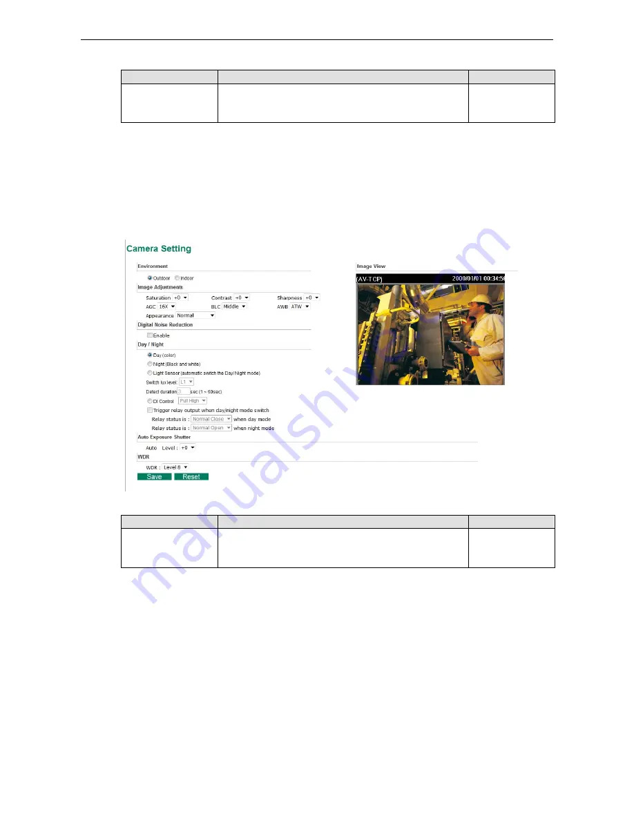
Camera Setting 

A few camera parameters can be configured for improving image quality according to the environment. 


Environment 
Setting 

Description 

Default 

Environment 

Choose what kind of environment will VPort camera be 
installed, optimized parameters will be applied to best fit your 
choice 


Outdoor 


Summary of Contents for VPort 26A-1MP Series

Page 1: ...Moxa VPort 26A 1MP User s Manual Edition 2 1 December 2015 www moxa com product 2015 Moxa Inc All rights reserved...

Page 2: ...to this manual or to the products and or the programs described in this manual at any time Information provided in this manual is intended to be accurate and reliable However Moxa assumes no responsi...

Page 3: ...peripherals You may also refer to Chapter 1 under Product Description and all of Chapter 2 of this manual The VPort 26A 1MP IP Camera has been designed for various environments and can be used to buil...

Page 4: ...lay Control 3 4 Snapshot 3 4 4 System Configuration 4 1 System Configuration by Web Console 4 2 System 4 3 General Settings 4 3 Account Privileges 4 4 Local Storage 4 5 System Log 4 6 System Parameter...

Page 5: ...4 38 Digital Input 4 39 Motion Detection 4 40 CGI Event 4 43 Camera Tamper 4 44 A Frequently Asked Questions A 1 B Modbus Address Table B 1 Read Write Registers Support Function Code 4 Function Code...

Page 6: ...sic video feeds many advanced features are also included to set up surveillance or web multimedia applications The VPort 26A 1MP is designed to provide stability robustness ease of use and flexibility...

Page 7: ...transmissions ensuring that images will not exhibit the mosaic effect Advanced network security functions such as 802 1x and SSH are also provided to prevent unauthorized access or data hijacking whi...

Page 8: ...with an SD card socket SDHC V2 0 for local storage and offline data logging in the event of network interruptions Currently the VPort 26A 1MP supports SD cards up to 32 GB RTSP for easy integration wi...

Page 9: ...rm Package Checklist The Moxa VPort 26A 1MP is shipped with the following items If any of these items are missing or damaged please contact your sales representative for assistance VPort 26A 1MP inclu...

Page 10: ...P and HTTP network transmission mode Supports RTSP streaming Supports IGMP ver 3 protocols for efficient network transmission Supports SNMP V1 V2C V3 for network system integration and management Supp...

Page 11: ...a video recording and management solution Free Moxa VPort SDK Plus with CGI Commands ActiveX Control and API support for third party developers ONVIF conformity for standardization and interoperabili...

Page 12: ...Moxa VPort 26A 1MP Introduction 1 7 Product Description Form Factor IP Camera Module...

Page 13: ...nsor The VPort 26A 1MP includes a light sensor for detecting illumination which is for enabling the ICR IR cut filter removable function When the illumination is under 3 lux the image will be switched...

Page 14: ...tch No 2 is provided for enabling or disabling the LED light for users who do not want the LED light to be visible at night LED Description Power On power on Off power off 10 100 M Amber Ethernet link...

Page 15: ...f Test process runs When the rebooting process is finished the System LED will change to a green color 2 Restore to Factory Settings To restore the VPort 26A 1MP to the factory default settings press...

Page 16: ...n about how to install a VPort 26A 1MP IP camera The following topics are covered in this chapter Before Getting Started First Time Installation and Configuration Hardware Installation Software Instal...

Page 17: ...changes to the IP camera s configuration in addition to providing general access Administrators should read this part of the manual carefully especially during installation First Time Installation and...

Page 18: ...conduit hole use the side conduit hole as example b Prepare the cable gland if required c Use the cable gland to assemble the cables NOTE When installing the cable gland make sure the 2 rubber rings...

Page 19: ...and DI DO Audio lines if used NOTE Be sure to arrange the cables carefully to make sure that all cables are connected properly We recommend connecting the Ethernet cable first and then the 9 pin termi...

Page 20: ...ions drill a hole slightly smaller than the supplied screw anchors Step 3 Put anchors into these drilled holes Step 4 Fasten the bottom case with the four self tap screws b Mounting on the accessory s...

Page 21: ...IP Camera Module with the bottom case Step 6 To get the desired video image adjust the angles and zoom strength a Pan adjustment b Tilt adjustment c Rotate adjustment NOTE Do not grasp the lens when...

Page 22: ...wered on the POST Power On Self Test will run for a few moments The System LED will turn green when the POST is complete The 10 Mbps or 100 Mbps LED will then flash as the IP address is assigned The n...

Page 23: ...ress in the web browser s address input box and then press enter Step 3 Install the ActiveX Control Plug in A security warning message will appear the first time you access the VPort s web based manag...

Page 24: ...e installation details For details about configuration settings check the User s Manual on the software CD NOTE After accessing the VPort 26A 1MP s web based manager administrators should access Syste...

Page 25: ...d devices If power wiring and device wiring paths must cross make sure the wires are perpendicular at the intersection point NOTE Do not run signal or communications wiring and power wiring in the sam...

Page 26: ...for the first time The following topics are covered in this chapter Functions Featured on the VPort s Web Homepage VPort s Information IP Camera Name Camera Image View Audio Control Client Settings S...

Page 27: ...compatibility with the ActiveX Plug in VPort s Information This section shows the VPort s model name server name IP address MAC address and firmware version IP Camera Name A server name can be assigne...

Page 28: ...rwise the multicast video transmission will not be successful RTSP Enable the multicast video stream to be sent in RTSP control which means the multicast video stream will be sent only it receives the...

Page 29: ...x FPS frames per second and current FPS Status Users can select the target camera image to view each camera s video performance Show PTZ Control Panel only supported by non onvif version firmware V1 x...

Page 30: ...the hardware the next step is to configure the VPort 26A 1MP s settings Users can configure by web console The following topics are covered in this chapter System Configuration by Web Console System N...

Page 31: ...Dynamic DNS service UPnP Enable UPnP function Multicast Setting Set up Multicast IGMP Streaming Accessible IP Set up a list to control the access permission of clients by IP address SNMP Configure th...

Page 32: ...On the General Settings page administrators can set up the video Server name and the Date and Time which is displayed in the image s caption Server name Setting Description Default Max 40 characters U...

Page 33: ...rver for changing VPort s date and time setting in a given period NOTE Select the Automatic option to force the VPort to synchronize automatically with timeservers over the Internet However synchroniz...

Page 34: ...tion None Password Type a specific password for user authentication Privilege Check the function boxes to assign privileges for users in Control Relay1 NOTE The FPS of the video stream will be reduced...

Page 35: ...the VPortfolder folder Each recorded file is 10 seconds of video These are AVI files for playback in a popular media player NOTE Due to file system limitations the maximum number of files is 16584 Wh...

Page 36: ...The System Parameters page allows you to view all system parameters which are listed by category The content is the same as the VPort s sys_config ini file Administrators can also save this informati...

Page 37: ...boot The reboot process is finished once the STAT LED is lit continuously in green NOTE Upgrading the firmware will not change the original settings Reset to Factory Default From the Reset to Factory...

Page 38: ...sign a fixed IP Setting Description Default DHCP Get the IP address automatically from the DHCP server DHCP DHCP Auto configure Get the IP address automatically from the DHCP server and download the c...

Page 39: ...vice installation Follow the steps below to use the auto configuration function via Opt 66 67 Step 1 When VPort 26A 1MP enables the auto configuration function it will ask for the IP address from DHCP...

Page 40: ...environments HTTP Setting Description Default HTTP Port 80 or 1024 to 65535 HTTP port enables connecting the VPort to the web 80 HTTPS port 80 or 1024 to 65535 HTTPS port number for communication enc...

Page 41: ...yer and select Media Open network streaming Step 2 When the following pop up window appears type the URL in the input box E g type rtsp VPort s IP address RTSP Port udpstream_ch1_stream 1 or 2 rtsp VP...

Page 42: ...ayer compared to viewing it directly from the VPort s built in web server In addition viewing the VPort s video from the VLC player through a router or Internet gateway could result in a broken connec...

Page 43: ...assword to be authenticated None 1st SMTP password None 1st Sender s email address For security reasons SMTP servers must see the exact sender email address None NOTE Note that if the Sender s email a...

Page 44: ...e provider based on the rules of DDNS websites None Password Key None NOTE Dynamic DNS is a very useful tool for accessing a VPort over the Internet especially for xDSL connections with a non fixed IP...

Page 45: ...ent classification of the entire network The VPort s ToS capability improves your industrial network s performance and determinism for mission critical applications Setting Description Factory Default...

Page 46: ...t up correctly a multicast can only be sent to an end station or a subset of end stations on a LAN or VLAN that belongs to the relevant multicast group Multicast group members can be distributed acros...

Page 47: ...delivered correctly and precisely To learn more about IGMP Snooping refer to the Moxa EtherDeviceTM series Industrial Ethernet Switch user s manual Configuring Multicast Settings Setting Description D...

Page 48: ...URL address with complete CGI commands Ex http http event server Port CGI_Name Blank User name The account name for accessing the HTTP server Blank Password The password for accessing the HTTP server...

Page 49: ...his parameter Only one host with a specific IP address can access the VPort Enter IP address 255 255 255 255 e g 192 168 1 1 255 255 255 255 Hosts on a specific subnet can access the VPort Enter IP ad...

Page 50: ...otocol Version Security Mode Authentication Type Data Encryption Method SNMP V1 V2c V1 V2c Read Community Community string No Use a community string match for authentication V1 V2c Write Read Communit...

Page 51: ...o read and write MIB files User privilege only allows reading the MIB file but does not authorize writing to the file Root Auth Type For SNMP V1 V2c V3 and V3 only Setting Description Default No Auth...

Page 52: ...is the enterprise value 8691 8 4 13 This number cannot be changed NOTE The MIB file is MOXA VPORT26 MIB mib or my You can find it on the software CD or the download center of the Moxa website NOTE To...

Page 53: ...n SCADA systems To transmit Modbus over a TCP IP network a standard Modbus TCP protocol is provided With the support of the Modbus TCP protocol the SCADA HMI system can directly communicate with the V...

Page 54: ...Configuration 4 25 EAP PEAP MSCHAPv2 EAP TLS NOTE Please consult an expert or your network administrator for the configurations of 802 1X if you have trouble in it Telnet Use this option to Enable Di...

Page 55: ...the VPort s web interface you can enable or disable LLDP and set the LLDP transmit interval In addition you can view each VPort s neighbor list which is reported by its network neighbors Most importa...

Page 56: ...ge Appearance Position The position of the Image Appearance window can be changed by configuring Position X 0 to 400 and Position Y 0 to 300 Camera Setting A few camera parameters can be configured fo...

Page 57: ...or in the real environment with normal lighting Step 2 Select AWB in the page and then press Save Step 3 Move the camera back to the scene you are going to watch Then select the ATW for correcting the...

Page 58: ...e for the network to bear and in that condition VPort IP camera is able to automatically allocate available bandwidth to those parts of video that of your bigger interest For example when watching a f...

Page 59: ...ra can send a maximum of three simultaneous video streams two H 264 and one MJEPG In fact the VPort IP camera has two encoder engines The first encoder engine can generate one H 264 video stream and t...

Page 60: ...ze are provided The administrator can choose each option with NTSC or PAL modulation 1280x720 Resolution NTSC PAL WXGA 1280x800 1280x800 HD 1280x720 1280x720 SVGA 800 x 600 800x 600 Full D1 720 x 480...

Page 61: ...t loss occurs images will show a mosaic effect For this reason the VPort 26A 1MP supports an advanced CBR Pro function which can enable the flow control of image packets to ensure no packet loss for l...

Page 62: ...gital PTZ Before use digital PTZ you need to enable digital PTZ function in VPort 26A 1MP setting page as shown below First check enable then choose the PTZ function you are like to operate Note that...

Page 63: ...affic For example the frame rate can be set low during regular streaming to reduce bandwidth usage and automatically switch to a high frame rate during triggered events to ensure quick transmission of...

Page 64: ...5 seconds After 5 seconds the frame rate will return to the Live status setting 5 seconds Trigger Channel To enable or disable the video channels Disabled Alarm System In addition to the LED indicato...

Page 65: ...ess than the time needed to take a snapshot after an event post event image Send Alarm with Snapshot images Setting Description Default Take snapshot seconds s before the event A snapshot image is tak...

Page 66: ...o return the relay s status back to the system defaults To enable the function check the Override Relay 1 warning setting box and then click on Save In addition in the Relay Active behavior section yo...

Page 67: ...ms are active based on weekly schedule 3 Select the weekday 4 Set the start time 5 Set the duration this event will be active 6 Save Event Alarm Four kinds of event alarm are provided by the VPort for...

Page 68: ...hot image via E mail Once this DI is triggered the VPort will send the snapshot images set in the Event Alarm Basic page to the E mail addresses which are set in the Network SMTP Server page Disable S...

Page 69: ...isabled Show alert on the image when VMD is triggered Enable or disable the show the alert which when enabled displays a red square frame on the video image of the VMD alarm notification Disabled Show...

Page 70: ...the administrator can see the motion detection real time status and the change in percentage of the VMD area on the video image If the motion status and change of percentage are just what the administ...

Page 71: ...ect the HTTP event server for sending the HTTP action Disabled Blank text box For customizing the message to the HTTP event server Blank How to Configure a VMD alarm Step 1 Check the Enable VMD alarm...

Page 72: ...escription Default Enable CGI Event alarm Enable or disable CGI Event alarm Disable Event Select the Event 1 2 3 4 5 Disable Trigger Relay1 alarm Once this CGI Event is triggered the Relay alarm will...

Page 73: ...d be affected before camera tamper alarm is triggered 30 Duration How long should the camera tamper behavior persist before alarm is triggered 5 sec Trigger Actions Setting Description Default Enable...

Page 74: ...vent sever in this column Blank Once the configurations are done a purple box will appear in the right top corner of the image to indicate that environmental learning is underway the procedure should...

Page 75: ...does not support streaming technology If your system does not allow installation of plug in software the security level of the web browser may need to be lowered It is recommended that you consult th...

Page 76: ...s designed for surveillance purposes and has many flexible interfaces The user authentication and special confirmation when installing can keep the video encoder from unauthorized access You may also...

Page 77: ...Vender Name R moxa 0x0030 20 Product Name R VPort 36 1MP 0x0050 1 Serial Number R R R R 0x0051 2 Firmware Version 0x0053 2 Release Date 0x0055 2 MAC Address 0x0080 1 DI Status R 1 High 0 Low 0x0084 1...

Page 78: ...00 Saskatchewan GMT 05 00 Bogota Lima Quito GMT 05 00 Eastern Time US Canada GMT 05 00 Indiana East GMT 04 00 Atlantic Time Canada GMT 04 00 Caracas La Paz GMT 04 00 Santiago GMT 03 30 Newfoundland GM...

Page 79: ...06 00 Sri Jayawardenepura GMT 06 30 Rangoon GMT 07 00 Bangkok Hanoi Jakarta GMT 07 00 Krasnoyarsk GMT 08 00 Beijing Chongqing Hongkong Urumqi GMT 08 00 Taipei GMT 08 00 Irkutsk Ulaan Bataar GMT 08 00...

Page 80: ...X 8X 16X 32X 64X Flickerless Control Indoor Outdoor modes Black Level Control High Medium Low Auto Exposure Level 5 Image Rotation Flip Mirror and 180 rotation Image Setting Manual tuning with saturat...

Page 81: ...Indicators STAT Indicates if the system is booted properly or not Network 10 Mbps or 100 Mbps Power Power on off DIP Switch To turn the LED light on off Local Storage SD Socket Standard SD socket SDH...

Page 82: ...4 6 CS Level 3 EN 61000 4 8 EN 61000 4 11 Shock IEC 60068 2 27 Freefall IEC 60068 2 32 Vibration IEC 60068 2 6 Vandal Resistance EN 62262 IK10 level MTBF mean time between failures Time 201 721 hrs D...

Reviews: