


NPort IA5000A Series
Web Console Configuration
5-14
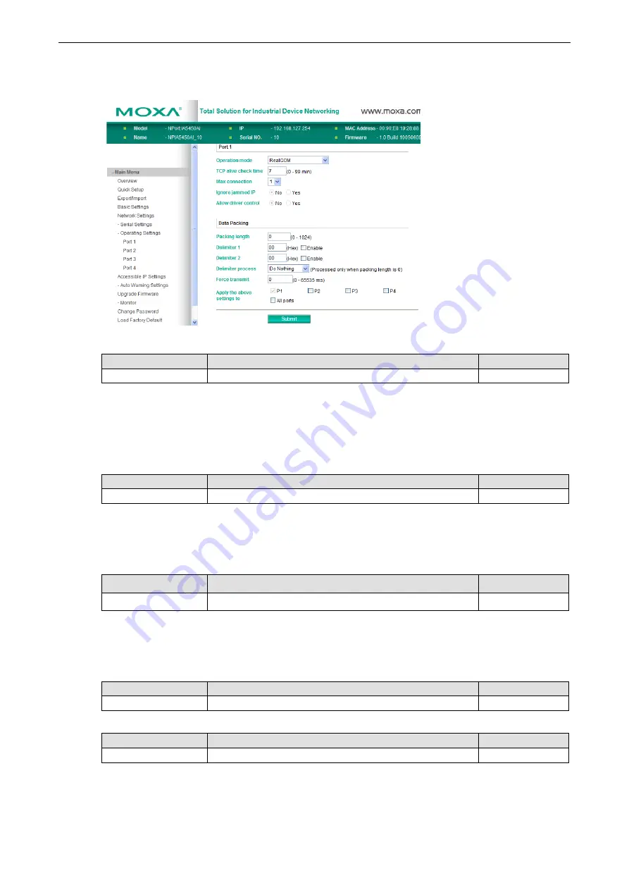
RFC2217 Mode
TCP alive check time
Setting
Factory Default
Necessity
0 to 99 min
7 min
Optional
0 min: TCP connection is not closed due to an idle TCP connection.
1 to 99 min: The NPort IA5000A automatically close the TCP connection if there is no TCP activity during this
given time. After the connection has closed, the NPort IA5000A will start “listening” for another host’s TCP
connection.
Local TCP port
Setting
Factory Default
Necessity
1 to 65535
4001
Required
The “Local TCP port” is the TCP port that the NPort IA5000A uses to listen to connections, and that other
devices must use to contact the NPort IA5000A. To avoid conflicts with well known TCP ports, the default is set
to 4001.
Packing length
Setting
Factory Default
Necessity
0 to 1024
0
Optional
Default = 0: The Delimiter Process will be followed, regardless of the length of the data packet. If the data
length (in bytes) matches the configured value, the data will be forced out. The data length can be configured
for 0 to 1024 bytes. Set to 0 if you do not need to limit the length.
Delimiter 1
Setting
Factory Default
Necessity
00 to FF
None
Optional
Delimiter 2
Setting
Factory Default
Necessity
00 to FF
None
Optional
Once the NPort IA5000A receives both delimiters through its serial port, it immediately packs all data currently
in its buffer and sends it out the NPort IA5000A’s Ethernet port.


