background image

ioLogik E1200H Series 

Using the Web Console 


3-19 

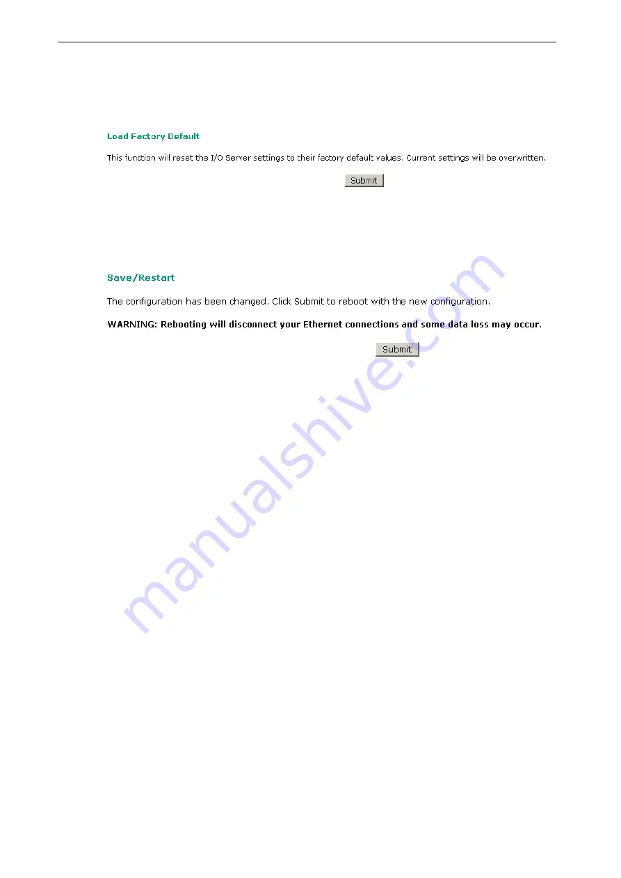
Load Factory Defaults 

This function will reset all of the ioLogik E1200H’s settings to the factory default values. All previous settings, 
including the console password will be lost.  


Save/Restart 

If you change the configuration, do not forget to reboot the system. 


Summary of Contents for ioLogik E1200H Series

Page 1: ...ioLogik E1200H Series User s Manual Edition 2 2 April 2018 www moxa com product 2018 Moxa Inc All rights reserved...

Page 2: ...s to this manual or to the products and or the programs described in this manual at any time Information provided in this manual is intended to be accurate and reliable However Moxa assumes no respons...

Page 3: ...I O Settings 3 8 DI Channels 3 8 DO Channels 3 10 AI Channels 3 11 AI Input Range 3 12 RTD Channels 3 14 System Management 3 16 IP Accessibility 3 16 Network Connection 3 17 Firmware Update 3 17 Impor...

Page 4: ...B Network Port Numbers B 1 C Factory Defaults C 1 D Pinouts D 1 E FCC Interference Statement E 1 F European Community CE F 1...

Page 5: ...connect sensors and on off switches for automation applications over Ethernet and IP based networks The following topics are covered in this chapter Product Model Information Product Features Inside t...

Page 6: ...ures IEC 60945 certification pending harsh maritime environment Wide temperature tolerance operates between 40 and 75 C 40 to 167 F Seamless SCADA connectivity with Active OPC technology User defined...

Page 7: ...ioLogik E1200H Series Introduction 1 3 Product Specifications NOTE The latest specifications for Moxa s products can be found at https www moxa com Physical Dimensions ioLogik E1261H Unit mm inch...

Page 8: ...ioLogik E1200H Series Introduction 1 4 ioLogik E1263H Unit mm inch...

Page 9: ...ou may then release the reset button LED Indicators Type Color Description PWR Green System power in ON Off System power is OFF RDY Green System is ready Green Blinking Located Green Red Blinking Safe...

Page 10: ...w to install the ioLogik E1200H The following topics are covered in this chapter Hardware Installation Connecting the Power Grounding the ioLogik E1200H Connecting to the Network I O Wiring Diagrams S...

Page 11: ...on the terminal block located on the top panel Connect the ground pin if earth ground is available Connecting to the Network The ioLogik E1200H has two built in Ethernet switch ports for connecting a...

Page 12: ...ioLogik E1200H Series Initial Setup 2 3 I O Wiring Diagrams...

Page 13: ...rogram Files MOXA IO Server Utility ioSearch 3 Search the network for the server On the menu bar select System Auto Scan Active Ethernet I O Server A dialog window will pop up Click Start Search to be...

Page 14: ...le Overview Network Settings General Settings Ethernet Configuration User defined Modbus Addressing Default Address AOPC Server Settings Tag Generation I O Settings DI Channels DO Channels AI Channels...

Page 15: ...gs in the navigation panel the main window will show a page of basic settings that you can configure You must click on the Submit button after making configuration changes The Submit button will be lo...

Page 16: ...w page contains basic information about the ioLogik E1200H including the model name serial number firmware version MAC address and current IP address Most importantly you can see the current I O statu...

Page 17: ...led by a remote PC due to network failure for example By default the Watchdog is disabled Users can configure how each output channel responds on the I O Settings page To enable the Watchdog check Ena...

Page 18: ...ATTENTION Disable the user defined modbus addressing function if using the MXIO NET library or using Active OPC Server to control or monitor the ioLogik E1200H s I O Status Default Address On this set...

Page 19: ...e www moxa com support After downloading the AOPC software unzip it and run Install exe The installation program will guide you through the installation process and install the Active OPC Server Utili...

Page 20: ...e Restart button on the next page On the Create AOPC Tag page click on the Create Tags button to push the tag configuration to Active OPC Server Launch the Active OPC Server program tags will be autom...

Page 21: ...Settings DI Channels The status of each DI digital input channel appears on the DI Channels page You can also configure each channel s digital input mode and parameters by clicking on the channel DI c...

Page 22: ...igger the counter The counter should be set to either start or stop If it is in stop mode the counter can be activated by the Modbus command Make sure that the Counter Filter is not set to 0 otherwise...

Page 23: ...e wave The Power On Setting field is used to specify the channel s configuration when the ioLogik E1200H is powered on and the Safe Status Setting field specifies the channel s configuration when the...

Page 24: ...ent status of each AI analog input channel can be viewed on the AI Channels page Click on a specific channel to enable or disable the AI channel by checking the Enable AI Channel box Auto Scaling and...

Page 25: ...t values BO default 2mA for selected ranges When input values are in the burnout range raw data will register as 0000h to indicate analog input burnout The definition of raw data is as follows Burnout...

Page 26: ...ioLogik E1200H Series Using the Web Console 3 13 The slope intercept function is used to compensate when the measurement requires a slight adjustment...

Page 27: ...access the RTD channel settings Select the Enable RTD Channel box and then select the sensor type that meets the physical attachment to the ioLogik E1200H The ioLogik E1200H allows you to calibrate th...

Page 28: ...he Web Console 3 15 The ioLogik E1200H allows you to manually adjust the current temperature reading In each channel configuration section select the channel apply the offset value and click the Submi...

Page 29: ...P address in the corresponding field enter 255 255 255 255 for the netmask To allow access to hosts on a specific subnet For both the IP address and netmask use 0 for the last digit e g 192 168 1 0 an...

Page 30: ...ging your devices Firmware Update Load new or updated firmware onto the ioLogik from the Firmware Update page Import System Configuration Settings Import a configuration into the ioLogik server from t...

Page 31: ...tion settings you will first need to enter the old password Leave this blank if you are setting up password protection for the first time To set up a new password or change the existing password enter...

Page 32: ...Factory Defaults This function will reset all of the ioLogik E1200H s settings to the factory default values All previous settings including the console password will be lost Save Restart If you chang...

Page 33: ...are covered in this chapter Introduction to ioSearch ioSearch Main Screen Main Screen Overview Main Items System Sort Quick Links Main Function Locate Firmware Upgrade Unlock Import Export Change IP A...

Page 34: ...ation Firmware upgrade for multiple ioLogik E1200H units same model Export configuration files from multiple ioLogik E1200H units Import a configuration file to multiple ioLogik E1200H units same mode...

Page 35: ...ive Ethernet I O Servers will search for ioLogik servers on the network When connecting for the first time or recovering from a network disconnection you can use this command to find I O servers that...

Page 36: ...ks are provided to search for I O servers on the network and sort the server list 1 Automatically search the local network 2 Sort by ioLogik E1200H s IP address connection 3 Sort by ioLogik E1200H mod...

Page 37: ...mote firmware upgrade function Enter the path to the firmware file or click on the icon to browse for the file The wizard will lead you through the process until the server is restarted Batch Upgrades...

Page 38: ...ress the Shift key select ioLogik and then right click Export The export function is used to export the current configuration file of an ioLogik E1200H The export file format will be ik12xx txt where...

Page 39: ...ices Users can batch modify IP addresses subnet masks and gateways for devices of the same model from a single window while submitting the changes at one time First select several devices of the same...

Page 40: ...ted ioLogik E1200H Restarting multiple ioLogik E1200H units is allowed Select the ioLogik E1200H and right click to process this function Reset to Default Select this function to reset all settings in...

Page 41: ...ioLogik E1200H Series Using ioSearch 4 9 Mass Deployment export Users can export E1200H series module information via ioSearch The export file format will be E1200H_Series_List...

Page 42: ...A A Modbus TCP Default Address Mappings The following topics are covered in this appendix E1261H Modbus Mapping E1263H Modbus Mapping...

Page 43: ...0 12 1 word R W DO Value 3 or 103 4xxxx 0x0020 8 1 word R W DO Pulse Operate Status 3 or 103 4xxxx 0x0040 NA 1 word R W DO WordValue Ch0 11 3 or 103 4xxxx 0x0100 8 1 word R W DI Counter Start 3 or 103...

Page 44: ...it CH0 DI Clear Count Value Read Always return 0 Write 1 Clear counter value 0 Return illegal data value 0x03 00290 0x0121 1 bit CH1 DI Clear Count Value Read Always return 0 Write 1 Clear counter val...

Page 45: ...input DI mode 00780 0x030B 1 bit DIO11 1 output DO mode 0 input DI mode 1xxxx Read only Coils Support function 2 Reference Address Data Type Description DI Channel 10001 0x0000 1 bit CH0 DI Value 0 OF...

Page 46: ...ad only 30040 0x0027 1 word CH3 DI Counter Value Lo Word Read only 30041 0x0028 1 word CH4 DI Counter Value Hi Word Read only 30042 0x0029 1 word CH4 DI Counter Value Lo Word Read only 30043 0x002A 1...

Page 47: ...ord CH0 DO Value 0 Off 1 On 40002 0x0001 1 word CH1 DO Value 0 Off 1 On 40003 0x0002 1 word CH2 DO Value 0 Off 1 On 40004 0x0003 1 word CH3 DO Value 0 Off 1 On 40005 0x0004 1 word CH4 DO Value 0 Off 1...

Page 48: ...0x0122 1 word CH2 DI Clear Count Value Read Always return 0 Write 1 Clear counter value 0 Return illegal data value 0x03 40292 0x0123 1 word CH3 DI Clear Count Value Read Always return 0 Write 1 Clea...

Page 49: ...Status 4 or 104 3xxxx 0x0600 3 1 word R RTD Value 3 or 103 4xxxx 0x0000 24 1 word R W DO Value 3 or 103 4xxxx 0x0020 8 1 word R W DO Pulse Operate Status 3 or 103 4xxxx 0x0040 NA 2 word R W DO WordVa...

Page 50: ...R W 00258 0x0101 1 bit CH1 DI Counter Operate Status 0 Stop 1 Start R W 00259 0x0102 1 bit CH2 DI Counter Operate Status 0 Stop 1 Start R W 00260 0x0103 1 bit CH3 DI Counter Operate Status 0 Stop 1 S...

Page 51: ...de 0 input DI mode 00772 0x0303 1 bit DIO3 1 output DO mode 0 input DI mode 00773 0x0304 1 bit DIO4 1 output DO mode 0 input DI mode 00774 0x0305 1 bit DIO5 1 output DO mode 0 input DI mode 00775 0x03...

Page 52: ...DI Value 0 OFF 1 ON Read only 10003 0x0002 1 bit CH2 DI Value 0 OFF 1 ON Read only 10004 0x0003 1 bit CH3 DI Value 0 OFF 1 ON Read only 10005 0x0004 1 bit CH4 DI Value 0 OFF 1 ON Read only 10006 0x000...

Page 53: ...only 30016 0x000F 1 word CH15 DI WordValue 0 OFF 1 ON Read only 30017 0x0010 1 word CH16 DI WordValue 0 OFF 1 ON Read only 30018 0x0011 1 word CH17 DI WordValue 0 OFF 1 ON Read only 30019 0x0012 1 wor...

Page 54: ...float 30533 0x0214 1 word CH2 Read AI Scaling Value Hi float 30534 0x0215 1 word CH2 Read AI Scaling Value Low float 30535 0x0216 1 word CH3 Read AI Scaling Value Hi float 30536 0x0217 1 word CH3 Read...

Page 55: ...Range RTD Channel 31537 0x0600 1 word CH0 RTD Value R 0 65535 Unit 0 1 Ohm Celsius Fahrenheit 31538 0x0601 1 word CH1 RTD Value R 0 65535 Unit 0 1 Ohm Celsius Fahrenheit 31539 0x0602 1 word CH2 RTD Va...

Page 56: ...H7 DO Pulse Operate Status 0 Off 1 On 40065 0x0040 1 word DO all Value Ch0 15 Bit0 Ch0 DO Value 0 OFF 1 ON Bit15 Ch15 DO Value 0 OFF 1 ON 40066 0x0041 1 word DO all Value Ch16 23 Bit0 Ch16 DO Value 0...

Page 57: ...value 0x03 AI Channel 40593 0x0250 1 bit CH0 AI 0 Mode 0 0 10V 2 4 20mA Bout 3 0 20mA 40594 0x0251 1 bit CH0 AI 1 Mode 0 0 10V 2 4 20mA Bout 3 0 20mA 40595 0x0252 1 bit CH0 AI 2 Mode 0 0 10V 2 4 20mA...

Page 58: ...1200H Network Port Usage Port Type Usage 80 TCP Web console service 502 TCP Modbus TCP communication 68 UDP BOOTP DHCP 4800 UDP Auto search 69 UDP Export import configuration file 9900 TCP Active OPC...

Page 59: ...s TCP Alive Check On Modbus TCP Timeout Interval 60 sec DI Mode DI Filter time 100 ms Trigger for counter Lo to Hi Counter status Stop DO Mode DO DO Safe Status Disable Power on status Disable Low wid...

Page 60: ...D D Pinouts Terminal Block Pin Assignments...

Page 61: ...ng interference that may cause undesired operation These limits are designed to provide reasonable protection against harmful interference when the equipment is operated in a commercial environment Th...

Page 62: ...F F European Community CE This is a Class A product In a domestic environment this product may cause radio interference in which case the user may be required to take adequate measures...

Reviews: