background image

[email protected]     www.motorvac.com

Safety During Service

Follow these safety instructions whenever the unit is being operated.

Consult Manufacturers Service Manual

Use manufacturer’s service manual for test procedures and fuel system specifications (i.e. fuel pressure).

Clean Spills Immediately.

Clean up all gasoline or detergent spills immediately and make sure to use a proper container for disposal.

Check All Fittings.

Check all fittings and fuel lines for leaks before, during, and after performing a cleaning service.

Secure Fuel Lines.

Keep fuel lines away from hot manifolds and all moving components.

Gas (Petrol) Service

First Time Operation


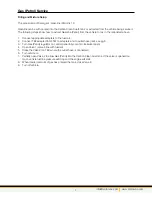
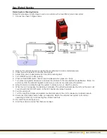
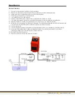
1.  Remove the filter from below the Gasoline (Petrol) tank and fill it completely with fuel and replace it on the 

unit

2.  Turn the Gas (Petrol) PRESSURE REGULATOR on the unit’s control panel counterclockwise until it is 

completely open.

3.  Attach the unit to the vehicle’s battery by connecting the red battery clip to the positive (+) battery 

terminal and the black battery clip to a solid ground point as far from the battery as possible. 

4.  Fill the reservoir on the Gas (Petrol) side (LHS when facing the front of the machine) with clean gasoline 

(petrol) until the tank level indicates 1/4 tank. See notes on page 8 for alternate filling procedure.

5.  Connect the output (red) hose and return (black) hose together by any 2 mating adapters. 
6.  Press the SERVICE SELECTOR switch to the left to select Gasoline (Petrol) FUEL SYSTEM SERVICE.
7.  Set the TIMER knob for five minutes (the pump will not run unless the timer is on)
8.  Press the ON/OFF switch to the ON position. NOTE: Alarm will sound continually until pump starts.
9.  Press and hold the START switch for a minute.
10.  Release the START switch and turn the ON/OFF switch to the OFF position.
11.  Disconnect the output and return lines.
12.  To drain the Gas (Petrol) disconnect the adapter from the return (black) hose.
13.  Direct the adapter on the end of the output (red) hose to an appropriate reservoir.
14.  Turn ON/OFF switch to ON position and press and hold START switch. When all the gas is pumped out 

release the START switch and turn the ON/OFF switch to the OFF position. 

15.  Dispose of the fuel in an environmentally approved method.

4

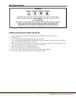
 WARNING

Flammable Liquid can squirt out of pressurized lines when connecting or disconnecting.

Verify that engine and machine are both off before connecting or disconnecting fuel  

lines or adapters.

Wear safety goggles.  

Wear chemical resistant gloves when connecting or disconnecting fittings and adapters.

Wrap a shop towel around pressure fittings and adapters when disconnecting.

Avoid exposure to flames, sparks, hot engine parts, and other ignition sources.

Explosion or flame or exposure to flammable liquid and vapors can cause injury.

The following process is used to flush factory testing fluids out of your new machine, and is only necessary 

before the first time you use the unit.

Summary of Contents for 500-0352

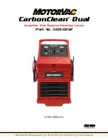
Page 1: ...1324 Blundell Rd Mississauga ON Tel 905 615 8620 Fax 905 615 9745 www motorvac com CarbonClean Dual Complete Fuel System Cleaning Center Part No 500 0352 USER MANUAL...

Page 2: ...pass harmlessly out through the exhaust system or are removed by the unit s fuel filter Removing contaminants from the combustion chamber creates a more even burn of fuel which improves horsepower inc...

Page 3: ...ration Fuel System Types Returnless Fuel System Filling and Mixture Setup Reservoir Filling Connection Vehicle Connection Procedure General Return System Cleaning Service Returnless System Connection...

Page 4: ...All of the controls hoses tank and filter are located on the left side of the machine Diesel Side All of the controls hoses tank and filter are located on the right side of the machine Adapter Storag...

Page 5: ...light is illuminated when on D Start button Press and hold to begin a service cycle Pressure must be greater than 5 psi to perform a service Green light illuminates when the pump is on E Service Selec...

Page 6: ...lack lead to the negative battery terminal 11 15 VOLTS DC Avoid Open Flames and Sparks Keep lighted cigarettes open flames or other ignition sources away from the battery Use Caution at All Times Use...

Page 7: ...any 2 mating adapters 6 Press the SERVICE SELECTOR switch to the left to select Gasoline Petrol FUEL SYSTEM SERVICE 7 Set the TIMER knob for five minutes the pump will not run unless the timer is on 8...

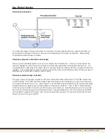
Page 8: ...ank A regulator maintains the correct fuel rail pressure by returning any excess fuel back to the tank These systems work by having a pressure regulator at the end of the fuel rail that returns any ex...

Page 9: ...being a dead end that only uses a small amount of fuel under conditions such as idling Returnless electronically controlled This type of system has pressure sensors at the fuel rail that feed back in...

Page 10: ...Connect TEE adapter 060 4501 to adapters and to outlet hose red see pg 8 3 Turn Gas Petrol regulator on control panel fully counter clockwise open 4 Open Valve 1 valve inline with fuel rail 5 Close th...

Page 11: ...info motorvac com www motorvac com 8 Gas Petrol Service Reservoir Filling Connection Return System Returnless System...

Page 12: ...the Gas Petrol side 7 Remove the vehicle s gas cap to relieve tank pressure 8 Connect the Carbon Clean Dual to the vehicle using appropriate adapters 9 Go to next service procedure step based on conn...

Page 13: ...to the manufacturer s specification Note On a return system the vehicle s regulator will ensure you cannot over pressurize the system 8 Allow the fuel to circulate through the system to clear any air...

Page 14: ...to the manufacturer s specification 8 Allow the fuel to circulate through the system to clear any air out Start the vehicle 9 When the run time expires the cleaning is complete The unit will automati...

Page 15: ...terminal and connect the black battery clip to a solid chassis ground 3 Pour 3 bottles of MV3D detergent into the diesel tank on the back right of the machine See pg 13 for alternate filling procedur...

Page 16: ...ppropriate adapters to the fuel rail 2 Connect TEE adapter 060 4501 to adapters and to outlet hose red see figure below 3 Turn Gas Diesel regulator on control panel fully counter clockwise open 4 Open...

Page 17: ...to the manufacturer s specification 8 Allow the diesel to circulate through the system to clear any air out Start the vehicle 9 When the run time expires the cleaning is complete The unit will automa...

Page 18: ...Tube 30 with Nozzle 100 5044 Spray Tube 6 100 5043 Included with Spray Nozzle Valve with 9 Siphon Tube 100 5019 Intake Cleaning Procedure using the ICS Kit Part 200 8667 and CarbonClean MV4 Intake Sy...

Page 19: ...nozzle once the tip of the spray tube gets near the throttle plate Note Do not spray outside of the throttle bore housing 14 If the MotorVac CarbonClean System is in use at the time press the STOP but...

Page 20: ...Symptom Solution The MCS 352 is not operational or trips breaker immediately Polarity is reversed on vehicle battery connection Check connections for correct polarity Check circuit breaker on the sid...

Page 21: ...info motorvac com www motorvac com...

Page 22: ...1324 Blundell Rd Mississauga ON Tel 905 615 8620 Fax 905 615 9745 www motorvac com ZIM15 01131 Rev1...

Reviews: