background image


Rev. 06/2022 

1 General Information ..................................................................................................... 4


1.1

 What Is the Purpose of these Assembly Instructions? ................................................. 4


1.2

 Who Are these Assembly Instructions Targeted to? .................................................... 4


1.3

 What Symbols Are Used in the Assembly Instructions? .............................................. 4


1.4

 Which Abbreviations/Acronyms Are Used in the Operating Manual? ........................... 5


2 Safety Instructions ..................................................................................................... 6


2.1

 Proper Disposal ...................................................................................................... 6


3 Intended Use ............................................................................................................... 7


3.1

 Functional Description ............................................................................................ 7


3.2

 Applications ........................................................................................................... 8


4 Product Description .................................................................................................... 9


4.1

 Technical Data ........................................................................................................ 9


4.2

 Warning Notices on the Device .............................................................................. 10


4.3

 Product Identification – Labeling on the Device ....................................................... 11


4.4

 Digression: Control of the Stepper Motor ............................................................... 12


4.5

 Overview Drawings ............................................................................................... 12


4.5.1

 50 Series ........................................................................................................... 13


4.5.2

 100 Series ......................................................................................................... 15


4.5.3

 140 Series .........................................................................................................  17


4.5.4

 150 Series ......................................................................................................... 19


4.5.5

 200 Series ......................................................................................................... 21


5 Wiring of the Device ................................................................................................... 23


5.1

 Connector Stepper Motor / Encoder ....................................................................... 23


6 Assembly Instructions ............................................................................................... 24


6.1

 Unpacking ............................................................................................................ 24


6.2

 Mounting the Device ............................................................................................. 24


6.3

 Connecting the Device .......................................................................................... 26


7 Errors ......................................................................................................................... 27


8 Maintenance ............................................................................................................. 28


8.1

 Customer Service Information ............................................................................... 28


8.2

 Returning Equipment for Repair / Inspection .......................................................... 28


8.3

 Instructions for Packaging the Equipment .............................................................. 28


8.4

 Spare Parts and Accessories ................................................................................. 28


Table of Contents 

Summary of Contents for ITB 100 Series

Page 1: ...ITB Throttle with Integrated Stepper Motor P N 30 43 xxx Assembly Instructions P N 01 50 034 Rev 06 2022...

Page 2: ...CH logo are registered and or common law trademarks of the MOTORTECH GmbH All further trademarks and logos displayed or used in this publication are the property of the respective entitled person and...

Page 3: ...arning Notices on the Device 10 4 3 Product Identification Labeling on the Device 11 4 4 Digression Control of the Stepper Motor 12 4 5 Overview Drawings 12 4 5 1 50 Series 13 4 5 2 100 Series 15 4 5...

Page 4: ...certain level of technical knowledge with respect to the operation of stationary engines and basic knowledge of the electronic components used are necessary Persons who are only authorized to operate...

Page 5: ...e used in the assembly instructions Abb Term Description Explanation CPR Counts Per Revolution Counter results per revolution Unit for the resolution of encoders HT High temperature Device version des...

Page 6: ...off the engine prior to assembly and secure it from re starting in order to avoid damage or injury Risk of injury and destruction The engine must be equipped with an independent emergency shutdown sw...

Page 7: ...ts them in changing the opening of the throttle The speed and power of the engine are regulated in this way System Overview Example VariStep3 stepper motor driver Master control VariFuel gas mixer Fly...

Page 8: ...able for different gases and performance classes A high temperature version HT can be used for operation in front of the intercooler These permit a temperature of the medium flowing through of up to 2...

Page 9: ...litary style connector Climatic environmental conditions 20 C to 85 C 4 F to 185 F max 95 humidity without condensation Weight The weight depends on the type series and diameter of the throttle Series...

Page 10: ...4 53 Standard 7 5 kg 16 53 lbs 115 mm 4 53 HT 7 6 kg 16 76 lbs 120 mm 4 72 Standard 7 2 kg 15 87 lbs 120 mm 4 72 HT 7 3 kg 16 09 lbs 125 mm 4 92 Standard 6 9 kg 15 21 lbs 125 mm 4 92 HT 7 0 kg 15 43 l...

Page 11: ...he necessary numbers for unique product identification are on the device Nameplate ITB on the Throttle Body Abb Meaning P N ITB part number S N ITB serial number Stepper Motor Nameplate Abb Meaning P...

Page 12: ...e 2 8 A microstep operation mode 2 8 A full step operation mode 4 A microstep operation mode Step width 0 9 1 8 Recommended control 1 16 microstep operation mode 1 16 microstep operation mode Technica...

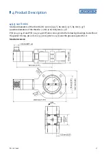
Page 13: ...tle D 42 mm 1 65 possible diameters of the throttle 41 mm 1 61 to 44 mm 1 73 P N 30 43 055 D and P N 30 43 055 D HT also correspond to the following drawings but without the gasket O ring 56 75 mm x 3...

Page 14: ...4 Product Description 14 Rev 06 2022 HT versions P N 30 43 050 D HT...

Page 15: ...hrottle D 60 mm 2 36 68 mm 2 68 possible diameters of the throttle 48 mm 1 89 to 68 mm 2 68 P N 30 43 105 D and P N 30 43 105 D HT also correspond to the following drawings but without the gasket O ri...

Page 16: ...4 Product Description 16 Rev 06 2022 HT version...

Page 17: ...le D 75 mm 2 95 80 mm 3 15 85 mm 3 35 possible diameters of the throttle 73 mm 2 8 to 85 mm 3 35 P N 30 43 145 D and P N 30 43 145 D HT also correspond to the following drawings but without the gasket...

Page 18: ...4 Product Description 18 Rev 06 2022 HT version...

Page 19: ...throttle D 90 mm 3 54 100 mm 3 94 possible diameters of the throttle 82 mm 3 23 to 104 mm 4 09 P N 30 43 155 D and P N 30 43 155 D HT also correspond to the following drawings but without the gasket O...

Page 20: ...4 Product Description 20 Rev 06 2022 HT version...

Page 21: ...110 mm 4 33 115 mm 4 53 120 mm 4 72 125 mm 4 92 possible diameters of the throttle 98 mm 3 86 to 125 mm 4 92 P N 30 43 205 D and P N 30 43 205 D HT also correspond to the following drawings but withou...

Page 22: ...4 Product Description 22 Rev 06 2022 HT versions P N 30 43 200 D HT...

Page 23: ...out using the original MOTORTECH harness via the 10 pin connector on the stepper motor Pin Description A Stepper motor phase A1 B Stepper motor phase A2 C Stepper motor phase B1 D Stepper motor phase...

Page 24: ...y Assembly instructions Required Accessories Connection cable for connection between the throttle and stepper motor driver VariStep stepper motor driver incl configuration software MICT and USB interf...

Page 25: ...four through bolts or threaded rods strength class 8 8 or higher to mount the butterfly valve between the two flanges Depending on the thread used observe the following tightening torques for strength...

Page 26: ...operation Follow operating manuals Follow the operating manual during connection and start up for the VariStep stepper motor driver and for the connected speed control 1 Connect the harness with the...

Page 27: ...ble Causes and Solutions Cause 1 The wiring between the VariStep stepper motor driver and ITB throttle is defective Solution 1 Check the connection harness and the connections to the stepper motor dri...

Page 28: ...th processing of your repair order Send the device with delivery note and return form to one of the two addresses below or to the nearest MOTORTECH representative MOTORTECH GmbH Hogrevestr 21 23 29223...

Page 29: ...Rev 06 2022 29...

Page 30: ......

Reviews: