background image

3 - 30 XR Series RFID Readers Integrator Guide

Advanced Configuration

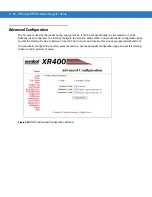
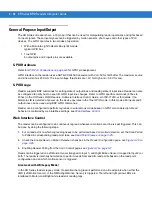
The Q value is used by the reader during query process. It can be set dynamically (by the reader) or can be 
statically (user) configured. To statically configure the Q value, select static in advanced reader configuration page 
and set the starting Q value to between 0 and 8. The minimum and maximum Q values are ignored with static Q.

To dynamically configure the Q value, select dynamic in advanced reader configuration page and set the starting, 
minimum and maximum Q value. 

 Figure 3-30

XR400 Advanced Configuration Window

Summary of Contents for XR400

Page 1: ...XR Series RFID Readers Integrator Guide ...

Page 2: ......

Page 3: ...XR Series RFID Readers Integrator Guide 72E 71773 08 Rev A December 2008 ...

Page 4: ...ion from Motorola The user agrees to maintain Motorola s copyright notice on the licensed programs delivered hereunder and to include the same on any authorized copies it makes in whole or in part The user agrees not to decompile disassemble decode or reverse engineer any licensed program delivered to the user or any portion thereof Motorola reserves the right to make changes to any software or pr...

Page 5: ...odels Updated Title to XR Series 04 Rev A September 2006 Added XR480 JP model Added Table 1 1 Read Capabilities Updated Appendix A Technical Specifications 05 Rev A June 2007 Updated Modify RFID Tags Chapter 3 Added Appendix C AR400 Differences 06 Rev A April 2008 Added the XR450 Added New Chapter 6 Security 07 Rev A October 2008 Added LLRP 08 Rev A December 2008 Updated Configuring Reader Propert...

Page 6: ...iv XR Series RFID Readers Integrator Guide ...

Page 7: ... Chapter 1 Getting Started Introduction 1 1 RFID Technology 1 1 RFID Components 1 2 Tags 1 2 Antennas 1 2 Readers 1 2 XR Series RFID Readers 1 3 Configuration and Upgrading 1 3 Tag Management 1 3 Ad Hoc Querying 1 3 Tag Filtering 1 3 Tag List 1 4 Event Management 1 4 Event Notification 1 4 Exception Notification and Heart Beat Notification 1 4 Device Management 1 4 Quick Backup and Recovery 1 4 SN...

Page 8: ... XR Series RFID Readers Ports 2 2 XR450 Mono Static Antenna Ports 2 2 Installation 2 3 Mounting Tips 2 3 Mounting the Reader 2 3 Connecting Antennas 2 4 Portal Setup 2 4 Powering the Reader 2 5 Verifying Hardware Functionality 2 5 Power On Test 2 5 Read Test 2 5 Communications Connections 2 6 Ethernet Connection 2 6 RS232 Connection 2 6 Reading Tags 2 8 Chapter 3 Administrator Console Introduction...

Page 9: ...ing SNMP Configuration 3 34 Network Status Event 3 34 Exception Events 3 34 Separate Read Points in Combined Groups 3 34 Selecting Event Notification Options 3 35 General Purpose Input Output 3 38 GPIO Hardware 3 38 GPIO Usage 3 38 Web Interface Control 3 38 Area mode with LIB Legacy Mode 3 38 Combined mode with LIB 3 39 Committing Discarding Changes 3 40 Managing Trusted Hosts 3 41 Managing Users...

Page 10: ...g Certificate To a Host PC 5 15 Export Certificate 5 17 Appendix A Technical Specifications Technical Specifications A 1 RFID Reader A 1 Cable Pinouts A 5 Ethernet Connections A 5 RS232 Port Connections A 5 GPIO Port Connections A 6 Appendix B Firmware Upgrade Procedures Introduction B 1 Prerequisites B 1 Auto Recovery B 2 Update Phases B 2 Update Method 1 Use a LAN B 3 Update Method 2 Direct Conn...

Page 11: ...Read Write also known as Class 0 Class 1 Read Write and Gen2 see Table 1 1 on page 1 2 for read write specifications XR400 is a multiprotocol reader XR440 XR450 XR480 EU XR480 JP are single protocol readers reading only Gen 2 Configurations This guide covers the following XR Series RFID reader configurations XR400 RFID Reader XR440 RFID Reader XR450 RFID Reader XR480 EU RFID Reader XR480 JP RFID R...

Page 12: ...ations between the reader and a remote client Chapter A Technical Specifications includes the technical specifications for the RFID reader Chapter B Firmware Upgrade Procedures describes how to upgrade the reader with new firmware Chapter C Feature Differences From The AR400 describes AR400 feature differences Notational Conventions The following conventions are used in this document RFID Reader r...

Page 13: ...r Call the Support Center from a phone near the scanning equipment so that the service person can try to talk through the problem If the equipment is found to be working properly and the problem is readability the Support Center will request samples for analysis at our plant If the problem cannot be solved over the phone the equipment may need to be returned for servicing If that is necessary spec...

Page 14: ...xii XR Series RFID Readers Integrator Guide ...

Page 15: ...n RFID tag contains a circuit that can store data This data may be pre encoded or can be encoded in the field The tags come in a variety of shapes and sizes A typical RFID system consists of transponders called tags readers and antennas To read a tag the reader sends out radio frequency waves using attached antennas This RF field powers and charges the tags which are tuned to receive radio waves T...

Page 16: ...to send data and are available with two power options Active Tags are typically powered by light weight batteries and have limited life Passive Tags are powered by the RF field generated by the RFID reader Passive tags are much lighter less expensive and have a much longer life than active tags Antennas Antennas are used to transmit and receive radio frequency signals A read point is the RF range ...

Page 17: ... RFID solutions Configuration and Upgrading The reader is easily to reconfigure using the Administrator Console The reader can also accept new firmware and configuration updates Tag Management Ad Hoc Querying Use ad hoc querying to send a query about tag visibility The reader replies with Tag s Visible Not Known never seen or imported or Not Visible previously seen but now missing with last seen t...

Page 18: ...der using the Administrator Console SNMP Integration The reader can send real time notification of specific events and failures to the SNMP server Security Trusted Hosts Use the Trusted Hosts security feature to prevent unauthorized network hosts from communicating with the reader This feature restricts access to the list of allowed host IP addresses User Level Security The reader recognizes three...

Page 19: ...Class1 G2 EPC Tag ID write function has been added Kill Operation The Class1 G2 Kill Command implements the Kill command Kill Code Write command and a new Kill Specific command in the Class1 G2 protocol Lock Operation The Class1 G2 permanent EPC Tag ID is supported Table 1 2 LED Indications LED Description Green Solid Flashing Reader is powered on Reader shutdown and or image load Red Error condit...

Page 20: ... from a DHCP server automating the IP address and default Gateway configurations Flexible Read Point Configurations Connect up to eight antennas four transmit and four receive to a single reader This decreases the per read point cost Logically combine antennas to create a single wide read point with a much greater range than that of a single antenna Physical Interfaces At the physical layer the XR...

Page 21: ...ns Figure 2 1 XR Series RFID Readers Physical Connections Antenna Reverse TNC USB Client RS232 Power LEDs USB Host Mounting Tabs Mounting Tabs Reset Button GPIO 10 100BaseT Ethernet CAUTION Use only the XR Series RFID readers provided parts or parts approved recommended by Motorola Substituting other cables or parts may degrade system performance damage the reader and or void the warranty ...

Page 22: ...ty Table 2 1 XR Series RFID Readers Port Descriptions Port Description Antenna Reverse TNC Connect up to eight antennas four transmit TX four receive RX Also use the four TX ports as TX RX ports in single port mode The XR450 RFID reader only configuration also includes four mono static antenna ports 10 100BaseT Ethernet Insert a standard RJ45 Ethernet cable for connection to an Ethernet network In...

Page 23: ...ow a minimum of five inches of clearance on all sides of the reader Mounting the Reader 1 Position the reader on the wall or shelf ensuring a minimum clearance of five inches on all sides Orient the reader vertically with the ports at the bottom and ensure that all connected cables hang straight down 2 Mark the hole locations using the mounting tabs as a guide see Figure 2 2 Remove the reader and ...

Page 24: ...ion for the XR450 is the same except that the XR450 can be run in mono static mode which only requires one antenna for both transmit and receive Portal Setup In portal situations dock doors set the TX for an antenna on one side of the portal to face the TX of the opposing antenna except for the XR450 in mono static mode Similarly ensure that the antenna RXs face each other Figure 2 4 Portal Alignm...

Page 25: ...ower LED lights when the reader completes power up and is operational Read Test After the reader powers up test the read range to verify that it meets requirements 1 Enable polling using the web based Administrator Console See Scan Control on page 3 7 2 Control the reader through a real time application 3 Present a tag so it is facing the antenna and slowly approach the antenna until the reader ye...

Page 26: ...nsole login window appears 4 Log in to the Administrator Console the reader settings such as the IP address can be changed See Chapter 3 Administrator Console RS232 Connection Serial communication allows the Administrator Console to be accessed using terminal software to change reader settings Use this method of administration rather than the Web based method in the following situations When the I...

Page 27: ...etting enter the menu number press Enter then enter the new configuration value For example to change the IP address enter 2 to select IP Address press Enter then enter a new IP address value 16 To save the settings to the reader enter 13 then press Enter to apply the change The host displays the Current Configuration menu Current Configuration Serial Number C80507AF8280442D MAC Address 00 A0 F8 C...

Page 28: ...Reading Tags To connect the reader to a host computer and read tags in real time Connect through Ethernet TCP IP and use a real time application to display the tags or the tags can be seen on the reader Query Tag page see Query Tags on page 3 12 ...

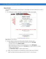
Page 29: ... this is the first time the reader has been accessed enter admin in the User Name field and change in the Password field For units that require immediate Region Selection the Region Control window appears see Figure 3 2 on page 3 2 NOTE The screens and windows are provided for illustration purposes only and may differ from actual screens The applications described may not be available on or applic...

Page 30: ...pears proceed to step 5 and follow the prompts to enter the new password Figure 3 2Region Selection Prompt Window NOTE To find the IP address see RS232 Connection on page 2 6 to display the Current Configuration menu see Figure 2 5 on page 2 7 NOTE The screens are provided for illustration purposes only and may differ from some of the actual product screens Procedures are not product specific and ...

Page 31: ... drop down menu and click on Set Country Click on the appropriate scan frequencies and click on Set Scan Mode Frequencies Click the I understand check box Click Commit Region Change to complete the Region Selection 4 The Region Control Reinitializing window appears while the unit is initializing see Figure 3 4 on page 3 4 Figure 3 3Region Control Window ...

Page 32: ...rd change window appears and prompts the user to change the password Enter and confirm the new password then click Change Use this new password for subsequent visits to the console The reader Administrator Console Main Menu window appears see Figure 3 5 Figure 3 5Reader Administrator Console Main Menu ...

Page 33: ...oft reboot from the reader Maintenance Console saves and restores the tag events and the system log when the reader comes back up again NOTE To reset the reader back to the factory default settings press and hold the reset button seeFigure 1 1 on page 1 1 for reset button location for 5 seconds or more This also resets the password and reader configuration NOTE Hard rebooting the reader disconnect...

Page 34: ...erational parent device For example when a reader is system disabled the read points are marked parent disabled Reader Information System Clock Weekday Month Day of the Month Hour Minute Second Year The reader system clock time Click to change the time System Up Time Number of Days Number of Hours Number of Minutes Number of Seconds The length of time that the reader has been running CPU Usage Per...

Page 35: ...led The polling state displays the current polling setting Enabled or Disabled If Polling is enabled from Admin console then the Polling State Enabled from Web message is displayed If polling is enabled from byte stream then the Polling State Enabled from byte stream message is displayed Figure 3 7Scan Control Window NOTE To initiate a scan for on demand read points click Initiate Scan To enable o...

Page 36: ...n antenna which is part of a combined antenna group then the same operation will be performed on other antennas in this group For example To combine antennas 1 and 2 in one group and antennas 3 and 4 into different group Define two read point classes such as Zone1 and Zone2 with a Type such as COMBINED1 and COMBINED2 Assign Zone1 to read points 1 and 2 and Zone2 to read points 3 and 4 Perform a re...

Page 37: ...eck for presence of a Motorola antenna To disable the antenna check do not check the Enable Antenna Check check box 1 Click Add Class The new class appears in the Class List 2 If the motion detectors are enabled see Configuring Reader Properties on page 3 28 select which motion detectors if any are used from the Motion drop down list 3 Click Commit Revert See Committing Discarding Changes on page ...

Page 38: ...hedule periodic scans The following window provides details about the read point Figure 3 11Read Point Configuration Window NOTE To enable all eight read points for transmit receive on XR480 or to enable transmit receive on the four TX ports on XR450 select the Single Port TX RX Mode check box see Figure 3 29 on page 3 28 ...

Page 39: ...h the new read point class 7 Click Modify Read Point then Commit Revert to apply the changes See Committing Discarding Changes on page 3 40 8 From the Options list click Scan Control The Reader Scan Control window appears Click the appropriate selection to Initiate Scan or Enable Polling Figure 3 12Reader Scan Control Window ...

Page 40: ...f read points where the tag is visible displays Querying a tag requires the tag ID and the type of tag To obtain the tag ID and type of all tags the reader is viewing 1 Enable polling at the reader and configure read point classes as polled classes 2 Open a new browser window and enter the following URL http Reader IP Address cgi bin dataProxy oper queryTags XML containing the tag ID and type of a...

Page 41: ... Timestamp Show port number Displays the Physical port Number in the tag list Show milliseconds Displays the millisecond count in the tag list Show rssi Only for gen2 tags the value displays the signal strength at which the tag was read Show Tag Rssi Only for Yellowstone Tags Indicates the signal power which Gen2 tag received from the reader To display the Tag RSSI in the query page in the Configu...

Page 42: ...ollowing functions Write Lock and Unlock RFID Tags see Write Lock and Unlock RFID Tags on page 3 15 Kill RFID Tags see Kill RFID Tags on page 3 17 Configure Yellowstone Tags see Configure Yellowstone Tags on page 3 18 Set Antenna Configuration Yellowstone Tags Read Lock Options Figure 3 15Modify RFID Tags Window ...

Page 43: ...on from the Read Point drop down list 5 If write is to be performed select the write check box 6 Enter the data in Data to Write field 7 Select any of the following memory banks or fields EPC The data is written in EPC bank from start word specified for Gen2 tags USER The data is written in user bank from start word specified for Gen2 tags The data is written to user field of Class0 tags from the ...

Page 44: ...assword and Access Password is locked for both read and write The locked tags can be accessed in secured mode with access password The lock operation is performed on Tag Id User Data and kill password of Class0 tag The class0 tags can not be unlocked Permanent Unlock Similar to Unlock but permanently unlocked Gen2 tags can not be locked again Permanent Lock Similar to Lock but permanently locked G...

Page 45: ...ration is performed in both legacy Gen2 tags If the kill password length is 3 bytes the kill operation is performed only in legacy tags 4 Select the antenna port to use for the write lock operation from the read point drop down list Tag Killing Tips Before killing tag consider the following tips The operation affects only the first visible selected legacy tag and all selected Gen2 tags Killing a t...

Page 46: ...owstone Tags Window 2 Enter the tag ID in the Select Tag ID field This field can be left blank for setting the back scatter strength for all yellow stone tags in the vicinity 3 Enter the access password if the antenna configuration operation to be performed on the Locked Yellow stone Tags Access password 00000000 is the default setting 4 Select the antenna port to use for the antenna configuration...

Page 47: ...ntenna port to use for the read lock operation from the Read Point drop down list 5 Select the read lock option from the available radio buttons Unlock tag bank currently unlocked Perma Unlock permanently unlock the tag bank it can never be locked Lock tag bank reading locked Perma Lock permanently lock the tag bank it can never be unlocked 6 Select the memory bank check box s to select which memo...

Page 48: ...sociating a read point class to an antenna The following section describes these processes Creating a Filter Rule To create a filter rule 1 Set the Global Filter to select the type of tags type to be filtered 2 Click Tag Selection the Tag Selection Filter window appears Figure 3 21Tag Selection Filter Window 3 Click Create A New Rule the Tag Filter Rule window appears NOTE The Tag Selection Filter...

Page 49: ...Select the Match type rule to match the filter mask data provided in the filter mask field for the reporting tag For example if the filter data is 1234111100001111 and mask is FFFF000000000000 then the reader reports all tags that start with 1234 1234XXXXXXXXXXXX for a match type rule Select Exclude type rule to exclude the filter data provided in the filter mask field for the reporting tag For ex...

Page 50: ...vailable Rules list and click The rule moves to the Selected Rules list adding it to the filter 14 Click Add Modify Tag Filter The Tag Selection Filter window appears with the new filter in the Tag Filter List 15 Click Commit Revert to apply the changes See Committing Discarding Changes on page 3 40 16 Click on Read Point Class the Read Point Classes window appears ...

Page 51: ...ic Scan Read Point on page 3 8 for field descriptions 3 Select the new filter from the Tag Selection drop down list 4 Click Add Class 5 Click Commit Revert to apply the changes See Committing Discarding Changes on page 3 40 6 Click Configuration The XR400 provides up to four read points see Figure 3 9 on page 3 9 and the XR480 provides up to eight read points see Figure 3 10 on page 3 10 ...

Page 52: ... 25Modifying Read Point Configuration 8 Select the new class which contains the new filter from the Class drop down list 9 Click Modify Read Point The Reader Configuration window displays the new read point class associated with the selected antenna The selected read point now reports tags per the selected rule ...

Page 53: ...ith a different name The reader includes several read point classes to use as templates To create a new class based on one of the existing classes 1 Click Read Point Class the Creating a New Read Point Class window appears Figure 3 26Creating a New Read Point Class 2 Select a class from the Class List and click Select Class to display the class settings 3 Enter a new name in the Class Name field 4...

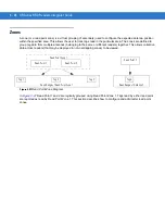
Page 54: ...same or different readers together This allows collective data across readers that may be deployed in non overlapping zones to be viewed Figure 3 27Read Point Zone Diagram In Figure 3 27 Read Point 1 and 2 are logically grouped using Read Point Zone 1 Tags read by either read point are reported as read by Read Point Zone 1 This section describes how to configure and administer read point zones Rea...

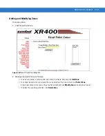
Page 55: ...point zones as follows To add a zone enter a name for the zone in the Zone Name field and click Add Zone To change the name of a zone select the zone name from the Zone List and click Select Zone Enter a new name for the zone in the Zone Name field and click Modify Zone to update the Zone List To delete the zone being modified click Delete Zone ...

Page 56: ...n Enter a description optional to help identify the reader Optional Payload Parameters Select Optional Payload Parameters which contains three fields Memory Bank Start word Length Reader can report one additional field apart from EPC configured using the optional pay load parameter setting For Class 0 tags if User Bank is selected full user data would be read Start and Length are ignored for Class...

Page 57: ...lows the administrator to disable the reader Enable Read on Motion Detection The Enable Motion Detector checkbox allows the administrator to enable tag reads in autonomous mode when motion sensors are triggered see General Purpose Input Output on page 3 38 Single Port TX RX Mode check box XR450 and XR480 only The Single Port TX RX Mode check box allows the administrator to enable RF transmit and r...

Page 58: ...configured To statically configure the Q value select static in advanced reader configuration page and set the starting Q value to between 0 and 8 The minimum and maximum Q values are ignored with static Q To dynamically configure the Q value select dynamic in advanced reader configuration page and set the starting minimum and maximum Q value Figure 3 30XR400 Advanced Configuration Window ...

Page 59: ...with a class and a read point zone The XR400 provides up to four read points see Figure 3 9 on page 3 9 and the XR480 provides up to eight read points see Figure 3 10 on page 3 10 Figure 3 31Modify Read Point Configuration Window 2 Enter a new name and description in the Name and Description fields or skip to leave the existing name 3 To associate the read point with a class and a read point zone ...

Page 60: ...ration that a tag has transient periods when it is changing visibility in the system set the Notify option to Moderated to smooth out temporary conditions and generate an event only when the tag is no longer being actively tracked The system still knows about the tag but it is not visible to any Read Point To disable notification for this type of event set the Notify option to Never the event is n...

Page 61: ...e fault is fixed the device cab be enabled Any device below it that was parent disabled is automatically brought back online Event Notification Preferences To set notification for a when particular events occurrence select subscribe to events via the Event Notifications page Event notifications may also be set to provide no event notifications Setting Event Notification Preferences To specify the ...

Page 62: ...ader receives a user disable status notification and the read point s associated with the reader receive a user disable parent notification Similarly if a device fault occurs for the reader all corresponding events for the device fault also occur for each read point associated with that reader After correcting the fault enabling the reader also enables parent disabled devices associated with it Ex...

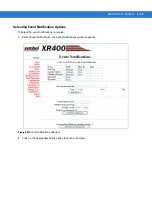
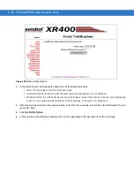
Page 63: ...Event Notification Options To select the event notifications to receive 1 Select Event Notifications the Event Notifications window appears Figure 3 32Event Notifications Window 2 Click on the appropriate Notify option for each event type ...

Page 64: ...ot filtered out Moderated retest this condition every minute up to the time out value If the condition still exists and an intervening event has not occurred provide notification for this event type if the event is not filtered out 4 If Moderated was selected in the previous step enter the time out value in seconds in the Moderated Timeout seconds field 5 Click Set Notify Option 6 In the main Even...

Page 65: ...t Zone pass through Class Exclusive Only events that do not occur in a specific Read Point Class pass through Read Point Exclusive Only events that do not occur in a specific Read Point pass through 8 Click Set Filter Option 9 To receive event notifications in the main Event Notifications window enter a valid link in the Host Notification Link field then click Set Host Link If this is not set or i...

Page 66: ...l 6 inputs and 6 output lines can be used using BSP GPIO commands Reader can be configured to perform tag reads in autonomous mode based on GPIO motion detection Read behavior is controlled by web interface settings see Web Interface Control Web Interface Control The reader can be configured to do continuous tag read whenever a motion senor line is kept triggered This can be done by doing the foll...

Page 67: ...sed the reads are triggered from the motion sensor of the lowest indexed read point in the combined group For example if combined group 1 combines read points 1 and 3 the reads in both antennas happen when the LMS from read point 1 is triggered The left yellow LED interfaced over Motorola LIB is ON when the LMS triggers antennas 1 2 5 6 and they are reading tags Similarly right yellow LED on Motor...

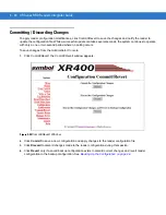
Page 68: ...od where no polling occurs To save changes from the Administrator Console 1 Click Commit Revert the Commit Revert window appears Figure 3 35Commit Revert Window 2 Click Commit to save a new configuration and apply changes to the reader configuration file 3 Click Discard to discard changes made to the reader configuration during this session 4 Click Revert only if a saved backup configuration exist...

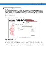
Page 69: ...e IP addresses of any computers that attempt to access the reader to provide a history of attempted accesses To manage trusted hosts 1 Click Trusted Hosts the Trusted Hosts window appears Figure 3 36Trusted Hosts Window 2 To add a trusted host to the list enter the IP address in the IP Address field then click Add Host 3 To delete a trusted host select the host address from the Current Trusted Hos...

Page 70: ...ter the user password in the Password field 4 Select an option from the Access Level drop down list for the new user View Allows the user to connect to the Administrator Console and view reader settings Edit Allows the user to make configuration changes excluding tasks such as updating the firmware Maintenance This provides administrator privileges and allows the user to access all functionality o...

Page 71: ... the user select the user from the User List select the Delete User radio button and click Modify User 4 To assign a new password to the user select the user from the User List select the Change Password radio button and click Modify User In the window that appears enter the old user password then enter and confirm the new password 5 To change the access level of the user select the Set to View On...

Page 72: ...lect the appropriate country from the country drop down menu and click on Set Country To enable scan mode click on Enable Scan Mode Select the appropriate scan frequency from the drop down menu and click on Set Frequency Select the EU 302 208 V1 2 1check box and click Set Version to set the EU 302 208 V1 2 1 version Click the I understand check box Click Commit Region Change to complete the Region...

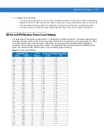
Page 73: ...ower setting of 0 Using the chart below the power level should be 0 04 watts The power level for both reading and writing tags is logarithmic with the maximum power about 30dbm This table describes the different values for different power levels The values are dBm Watts power Low end setting High end setting Table 3 5 Power Level Settings Output Power Full Power Power Level Value decimal dBm Watt ...

Page 74: ...3 46 XR Series RFID Readers Integrator Guide ...

Page 75: ...rk does not have a DHCP server To change the communication settings 1 Open a web browser 2 In the address bar enter the URL http followed by the IP address and press Enter 3 Log in using the administrator user name and password to access the Administrator Console 4 Click Maintenance the Reader Maintenance Console Main Menu appears Figure 4 1 Reader Maintenance Console Main Menu NOTE The screens an...

Page 76: ...figurable LLRP parameters on this page are 1 LLRP Client Mode LLRP Client Mode check box can be checked to operate LLRP in Client mode If LLRP Client mode is selected then LLRPClient IP and LLRPClient Server Port values will be used to connect to the client 2 Allow LLRP to Set Frequencies and LLRP Client Server Port When operating in LLRP server mode only the LLRP Port value is used as listening p...

Page 77: ...nt IP To select the LLRP Client mode check the LLRP Client Mode check box If LLRP Client mode is selected then LLRPClient IP and LLRPClient Server Port values are used to connect to the client When operating in LLRP server mode only the LLRP Port value is used as listening port of incoming requests from client Once the parameters are set they will persist across reader reboots NOTE When the reader...

Page 78: ...ed Deactivate LLRP disabled LLRP Server is Running LLRP Server is Running Connect LLRP or Disconnect LLRP Enable FTP Server Select whether to enable the FTP server on the reader Checked enabled unchecked disabled Web Server Select the port type HTTP Port Select the HTTP port User entered Default 80 HTTPS Port Select the HTTPS port User entered Default 443 LLRP Client Mode Check to select the LLRP ...

Page 79: ... and Time To set the date and time 1 Click Maintenance in the main Administrator Console window 2 Click Date Time the System Time Management window appears Figure 4 4 XR400 System Time Management Window Figure 4 5 XR480 System Time Management Window ...

Page 80: ...Zone NOTE SNTP Simple Network Time Protocol is an Internet standard protocol built on TCP IP that assures accurate synchronization to the millisecond of computer clock times in a network of computers NOTE It is essential to have a DNS server configured to be able to add SNTP server on this page If a static IP address is used enter a valid DNS server address in the TCP IP configuration If this addr...

Page 81: ...leshooting 4 7 Getting Firmware Version Number The Version Control window displays the current firmware version and allows upgrading to new firmware To view this window click Version Figure 4 6 XR400 Version Control Window ...

Page 82: ...l Setting Description XR400 Radio Frequency Regulation Region For the XR400 select a Radio Frequency Regulation region for the reader and click Set Region DSP Version The version of the DSP firmware DSP Loader Version The version of the DSP loader Monitor Version The version of the monitor utility OS Version The version of the operating system build Application Server Version The version of the ap...

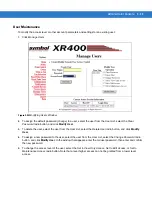
Page 83: ...can hold a maximum of 20 records Backing Up the Configuration The reader supports the following backup configuration functions Rolling back maintenance errors and restoring the reader to a particular date and time Pushing reader specific changes made to the config xml file to multiple readers simplifying multi reader management General configuration backup that can be restored when required such a...

Page 84: ...to the hard disk In Internet Explorer select File Save As 3 Click Save and use Windows Explorer to verify that the file is saved correctly Log Out Before closing the browser log out of the console Click Logout from either the maintenance menu or the main menu If unsaved changes are pending the Commit Revert window appears See Committing Discarding Changes on page 3 40 If the browser is left idle f...

Page 85: ...other reader configuration parameter s using the Administrator Console and the application expects the previous configuration Update the settings within the application Refer to the application manual Polling is enabled Some real time applications require disabling polling Refer to the application manual and if required disable polling using the Scan Control feature of the Administrator Console Se...

Page 86: ...4 12 XR Series RFID Readers Integrator Guide ...

Page 87: ...ty over BSP Byte Stream Protocol to protect the data transferred over Byte Stream For enhanced security a secure shell interface is provided for remote command line access to the reader and a secure file transfer service is provided for secure file transfers to or from the reader Secure HTTP enabled Administrative Web Console The HTTP based web console can be configured to work securely Once confi...

Page 88: ...1 Access the reader over HTTP http ip_address and login to the reader 2 Select Maintenance from Options list to bring up the Reader Maintenance Console page and select the Communication option to bring up the Communication Configurations page 3 In the drop down list for Web Server setting select HTTPS See Figure 5 3 on page 5 3 Figure 5 2 XR480 Communication Configuration Window ...

Page 89: ...ure 5 4 on page 5 3 Figure 5 4 Secure Service Settings Window To further access the reader over secure HTTP access reader using URL with https protocol prefix https ip_address_of_reader By default the XR Series reader uses self signed digital certificates for the reader HTTPS server authentication When accessing the reader using HTTPS over a web browser the certificate verification may prompt the ...

Page 90: ...5 4 XR Series RFID Readers Integrator Guide Figure 5 5 Certificate Warning Window Figure 5 7 displays the login page accessed in secure HTTPS mode Figure 5 6 HTTPS Login Page Window ...

Page 91: ...e Configuration page accessible from the Reader Maintenance Console see Figure 5 7 on page 5 5 Figure 5 7 Certificate Access Configuration Window Certificate Configuration page displays status of currently installed certificates and provides options to update the certificate see Figure 5 8 on page 5 6 NOTE Certificate Configuration is possible only when web console is accessed in secure mode i e o...

Page 92: ...th the reader over secure interface will use credentials for secure access as supplied by the new certificate NOTE Certificate update is done from a PKCS 12 format file pfx which contains the certificate and password protected private and public keys It is the password of this file that is given as input in PFX Password field during the certificate update process It is important that the certifica...

Page 93: ... connecting to the reader can be enabled by selecting the Enable Bytestream User Authentication option A secure network connection needs to be established by the client to reader server BSP port for this purpose Figure 5 10 Settings for Enabling Secure Byte Stream Window Secure custom applications can also be developed to interface to the BSP port Some options for developing the applications inclu...

Page 94: ...l option in Configuring Reader Shell Service to SSH Window displayed in Figure 5 11 Figure 5 11 Configuring Reader Shell Service to SSH Window Save the configuration and use an SSH 2 0 compatible client to connect to the reader Figure 5 12 on page 5 9 displays establishing a connection with PuTTY SSH client http www chiark greenend org uk sgtatham putty Figure 5 13 on page 5 10 displays a typical ...

Page 95: ...Security 5 9 Figure 5 12 Connection Using PuTTY Client Window ...

Page 96: ...ely to or from the reader The FTP Over Explicit TLS SSL Connection Setting Window see Figure 5 14 displays the establishing secure connection procedure using the FileZilla FTP client http filezilla project org Figure 5 14 FTP Over Explicit TLS SSL Connection Setting Window NOTE Secure file server on XR supports only Secure FTP over Explicit SSL TLS mode Use a compatible FTP client that supports th...

Page 97: ... a trusted third party The following steps describe how certificate is requested and issued from a Microsoft Certification Server 1 Access the certification server and select Request a certificate option see Figure 5 15 The Request a Certificate window is displayed see Figure 5 16 Figure 5 15 MS Certificate Request Welcome Window 2 Select the advanced certificate request option The Advanced Certif...

Page 98: ...bmit a request to this CA option and provide the required details see Figure 5 18 Figure 5 17 MS Advanced Certificate Request Window 4 For the Type of Certificate Needed the Server Authentication Certificate must be selected Figure 5 18 Advanced Certificate Request Window ...

Page 99: ...ark Keys As Exportable Window 6 Submit the request and wait for the certificate to be issued Select the issue option for the Certificate Management tool on the server typical procedure and the certificate is issued by the issuing authority see Figure 5 20 Figure 5 20 Certificate Issue Process Window ...

Page 100: ...rtificate is issued it is downloadable from the main certification page Select the Server Authentication Certificate date time from the Certificate Request Status window see Figure 5 21 to download the certificate Figure 5 21 Certificate Request Status Window ...

Page 101: ...ng the browser 1 Select the Install this certificate option see Figure 5 22 to install the issued certificate onto the PC from which the link is accessed Figure 5 22 Certificate Install Link Window 2 If the certification authority is not trusted warning s may display before the instillations see Figure 5 23 If this occurs confirm the installation Figure 5 23 Certificate Installation Process Window...

Page 102: ...5 16 XR Series RFID Readers Integrator Guide 3 Once certificate is installed on a host PC the following status is displayed see Figure 5 24 Figure 5 24 Certificate Installation Status Window ...

Page 103: ...ager tool accessible from Internet Options Certificates option 2 In the Certificates window select the Personal certificates tab and select the Export option see Figure 5 25 Figure 5 25 Certificate Installation Status Window 3 In the Certificate Export Wizard select the Export Private Key option and select Yes export the private key radio button see Figure 5 26 Figure 5 26 Private Key Export Enabl...

Page 104: ...s RFID Readers Integrator Guide 4 Select PKCS 12 format and set a password for the private key see Figure 5 27 and Figure 5 28 Figure 5 27 Select PKCS 12 Format Window Figure 5 28 Set Password For Private Key Window ...

Page 105: ...e the exported certificate see Figure 5 29 Figure 5 29 Set Password For Private Key Window 6 The Certificate Export Wizard completes the export and displays a success status see Figure 5 30 Figure 5 30 Certificate Exports Status Window ...

Page 106: ...5 20 XR Series RFID Readers Integrator Guide ...

Page 107: ...tics Dimensions 8 75 H x 11 75 W x 2 00 D 22 23 cm H x 29 85 cm W x 5 08 cm D Mounting Dimensions Mounting Holes 4 75 H x 12 73 W 12 05 cm H x 32 30 cm W Weight 5 lbs 2 27 kg Base Material Die Cast Aluminum Alloy Silver Paint LEDs Power Green Activity Yellow Error Red XR480 Environmental Specifications Operational Temperature EGQTS doc No SS 03800 74 and QU 10044 01 10 to 60 C 14 to 140 F Storage ...

Page 108: ...densing Vibration IEC 60068 2 6 Environmental Sealing IEC529 IP53 Connectivity Network 10 100BaseT Ethernet RJ45 connector Serial RS232 Serial DB9 connector Power 24 FTC 1 2 amps RF Connectors Reverse TNC Read Points Antennas 4 4 transmit 4 receive the 4 transmit read points can also be used as full transceivers Individual antennas can be combined logically into a single wide read point XR450 only...

Page 109: ... Models UHF band 902 928 MHz US UHF band 865 6 867 6 MHz EU UHF band 952 2 953 8 MHz JP Method Frequency Hopping Spread Spectrum FHSS Power Output Up to 30 dBm Air Link Protocol EPC Global see Table 1 1 on page 1 2 for reader settings Class 0 Class 0 Read Write Class 1 and Gen 2 EPC Gen 2 Dense Reader Mode Synchronization Network Time Protocol NTP IP Addressing Static and dynamic Host Interface Pr...

Page 110: ...A 4 XR Series RFID Readers Integrator Guide ...

Page 111: ...Direction Description Pin 1 TX P O TX Data Positive Rail Pin 2 TX N O TX Data Negative Rail Pin 3 RX P I RX Data Positive Rail Pin 4 NC No Connect Pin 5 NC No Connect Pin 6 RX_N I RX Data Positive Rail Pin 7 NC No Connect Pin 8 NC No Connect Table A 3 RS232 Connector DB9 9 Pin Pin Description Pin 1 NC Pin 2 TX Pin 3 RX Pin 4 NC Pin 5 Ground Pin 6 NC Pin 7 NC Pin 8 NC Pin 9 NC ...

Page 112: ...O Output Bit 4 3 EXT_GPIO_OUT2 O External GPIO Output Bit 2 4 EXT_GPIO_OUT0 O External GPIO Output Bit 0 5 EXT_GPIO_IN4 I External GPIO Input Bit 0 6 EXT_GPIO_IN2 I External GPIO Input Bit 0 7 EXT_GPIO_IN0 I External GPIO Input Bit 0 8 GND Ground 9 EXT_GPIO_OUT5 O External GPIO Output Bit 5 10 EXT_GPIO_OUT3 O External GPIO Output Bit 3 11 EXT_GPIO_OUT1 O External GPIO Output Bit 1 12 EXT_GPIO_IN5 ...

Page 113: ...rnet crossover cable There are six different types of firmware Each type performs unique changes to the current settings and each can be upgraded independently Available firmware versions include DSP Version DSP Loader Version Monitor Version OS Version Application Server Version FPGA Version Prerequisites The following items are required to perform the update procedure Reader with power supply La...

Page 114: ...here is not a specific order necessary when installing these files Determine which files need to be updated Auto Recovery The Auto Recovery feature allows the reader to recover flash images that have been corrupted due to a power outage during a software upgrade Two images of the Monitor are maintained and the bootstrap code determines the correct version to use The Monitor then determines if a so...

Page 115: ... the Console Main Menu select Scan Control the Reader Scan Control screen appears see Figure 3 12 on page 3 11 6 Select the Enable Disable Polling button to set Disable Polling The button reads Enable Polling when polling is disabled 7 Select Maintenance the Reader Maintenance Console see Figure 4 1 on page 4 1 appears 8 Select Version the Version Control screen appears and displays the current ve...

Page 116: ...ke up to 15 minutes Do not remove power to the reader or reboot the reader while update is in progress g The reader reboots itself when the update is complete h If the reader had been set up with a static IP address it restores the static IP address and reboots again i The reader could reboot a third time if the FPGA version has changed 10 Log onto the web console bring up the Version Control scre...

Page 117: ... the web based Administrative Console a Open a browser and type http 192 168 1 3 or the IP address of the reader to be upgraded if it is not the default address above The Reader Administrative Console login screen appears see Figure 3 1 on page 3 2 b Enter the user name and password If this is the first time accessing the console a prompt appears for a user name and password update The default set...

Page 118: ...supxr400 exe FlashUpdateUtility dll and Response txt files starts running Osupdate and shuts itself down Osupdate then downloads all the files specified in the Response txt file into RAM and if the download is successful starts writing the files to Flash If the ftp is not successful for any reason none of the files will be written into Flash e This update can take up to 15 minutes Do not remove po...

Page 119: ...erfaces and may generate support questions 3 The Serial Console can be entered by typing ARC instead of AdvancedReaderConsole Always This simplifies user command entry Typing AdvancedReaderConsole still works the way it did previously 4 The XR400 uses a different TagTracker rasm5dll dll file The turnaround time of TagTracker sending the read commands is important With the AR Series TagTracker send...

Page 120: ...parate Read Points in combined group is not implemented at the time Always A very small number of applications need this feature No work around 13 Disable HTTP is not honored until reboot Always Need to reboot to disable HTTP 14 The XR Series has a different response to the PurgeAllTags command AR400 sends the number of tags purged XR Series only says that the command is initiated Also if events a...

Page 121: ... 7 query 3 12 read point class 3 25 read point classes 3 8 read point zones 3 26 renaming reader 3 28 3 30 scan control 3 7 scheduling reads 3 8 setting date and time 4 5 status 3 5 trusted hosts 3 41 user maintenance 3 43 writing tag 3 14 antenna configuration for Yellowstone tags 3 18 antennas 1 2 installing 2 4 B backup 4 9 backup configuration 4 9 C cable pinouts ethernet A 5 GPIO A 6 RS232 A ...

Page 122: ... 2 6 mounting 2 3 portal 2 4 powering 2 5 RS232 connection 2 6 K kill RFID tags 3 17 L LEDs 1 5 error 2 5 power 2 5 lock options for Yellowstone tags 3 19 lock RFID tags 3 15 log out 4 10 logging 1 4 4 9 logging out 4 10 logs 4 9 M maintenance reader 4 1 user 3 43 managing the reader 3 1 managing users 3 42 mounting 2 3 P password 3 1 physical interfaces 1 6 pinouts ethernet A 5 GPIO A 6 RS232 A 5...

Page 123: ...and time 4 5 set Yellowstone tags 3 18 setting date 4 5 setting time 4 5 SNMP 1 4 3 37 SNTP set parameters 4 6 soft reboot 3 5 stop polling 3 7 synchronize clock 4 6 system log 4 9 T tags 1 2 filtering 3 20 management 1 3 reading 2 8 writing 3 14 time 4 5 troubleshooting 4 11 trusted hosts 1 4 3 41 U unlock RFID tags 3 15 updating firmware 1 3 user maintenance 3 43 V version control 4 7 W write RF...

Page 124: ...Index 4 XR Series RFID Readers Integrator Guide ...

Page 125: ......

Page 126: ...sville New York 11742 USA 1 800 927 9626 http www symbol com MOTOROLA and the Stylized M Logo and Symbol and the Symbol logo are registered in the U S Patent and Trademark Office All other product or service names are the property of their registered owners Motorola Inc 2008 ...

Reviews: