background image

CHANGE/VIEW

MTSX RSS

6-48

68P81074C50

MOTOROLA Radio Service Software
MTSX

Model:  

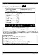
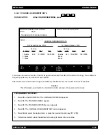
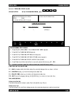
MAIN:CHANGE/VIEW:TRUNKING:SYSTEM

Use UP/DOWN Arrows to Select Type.

System ........................2

TRUNKING SYSTEM

System Key. ..................................Disabled
System Type..........................................II/IIi
System ID............................................0001

Alias............................................Disabled

Individual ID .....................................1-0001
Connect Tone (Hz)......................#0-105.88
Coverage Type..............................Disabled

Affiliation Type ................................On PTT
Dynamic Regrouping......................Enabled

Zone ................0

Chan ................0

Remote Monitor...............................Enabled

RM Base Time.......................................15

F1

HELP

F2

ADD

SYSTEM

F3

PREV

SYSTEM

F4

NEXT

SYSTEM

F5

DELETE

SYSTEM

F6

CONTROL
CHANNEL

F7

F8

F9

MORE

OPTIONS

F10

EXIT 

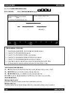
TRUNKING SYSTEM Screen for System 2, Type II/IIi

RSS LOCATION:

At the CHANGE/VIEW MENU, press                        .

F4

F3

A Trunking System refers to a specific repeater site, the system ID, the individual radio ID for that System, the
control channel frequencies, and the connect tone required to operate on that System.

Each system that the radio is programmed to operate on is ‘linked’ to one or more trunking personalities. The
personality defines the features available for the radio while operating on that system. Each radio is uniquely
identified on each system by its individual ID.

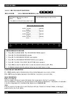
PROGRAMMING PROCEDURE:

1.

Press F4 at the MAIN MENU. The CHANGE/VIEW MENU appears.

2.

Press F4. The TRUNKING MENU appears.

3.

Press F3. The TRUNKING SYSTEM screen appears.

4.

Press Tab to select the desired field, or press the desired function key (F1 - F10).

5.

If a field is selected, press the up/down arrow keys to select choice or value.

Summary of Contents for SYMBOL MT2000 Series

Page 1: ...vd Ft Lauderdale FL 33322 Printed in U S A 11 96 All Rights Reserved RSS Technical Support Domestic 800 367 4803 Menu 5 International 305 475 3778 MT 2000TM MTS 2000TM MTX 838TM MTX 8000TM and MTX 9000TM MTSX Radio Service Software User s Guide Software Part Number RVN 4097 ...

Page 2: ...f RSS Diskette s 2 15 2 7 2 What To Do with Previous Versions of RSS Diskettes 2 16 2 7 3 Starting the RSS From the Hard Disk 2 16 2 7 4 Installing the RSS on Your Hard Disk 2 16 2 7 5 Installing the RSS on Multiple Computers or Networks 2 17 2 7 6 Hard Disk RSS Startup Procedure 2 17 2 7 7 The Banner Screen 2 18 2 7 8 The Main Menu 2 19 2 8 NAVIGATING THROUGH THE RSS MENUS 2 19 2 8 1 The Keyboard...

Page 3: ...he Scan List 3 10 3 2 12 Program the Personality Into the Codeplug 3 11 3 2 13 Program the Personality Into Archive and Backup Files 3 12 3 3 PROGRAMMING A BASIC MTX8000 TRUNKED RADIO 3 13 3 3 1 Desired Features 3 13 3 3 2 Major Decisions Involved 3 13 3 3 3 High Level Programming Flow 3 13 3 3 4 Step by Step Specific Programming Instructions 3 13 3 3 5 MTX8000 9000 Radio Button Switch Menu Item D...

Page 4: ...TMF Transmit Deviation 4 24 4 2 3 2 Transmit Signalling High Speed 4 26 4 2 3 3 Transmit Signalling MDC 1200 4 27 SECTION 5 GET SAVE PROGRAM MENU FUNCTIONS 5 1 INTRODUCTION TO SECTION 5 1 5 2 GET SAVE PROGRAM MENU 5 1 5 2 1 Reading Codeplug Data 5 3 5 2 1 1 Reading Codeplug Data From the Radio 5 3 5 2 1 2 Reading Codeplug Data From an Archive File 5 4 5 2 2 Get TCMS Ccodeplug update disk file 5 6 ...

Page 5: ...l Personality Using GE Star Signalling 6 87 6 2 3 2 1 Personality MDC Options 6 93 6 2 3 2 2 Conventional Personality Phone Options 6 96 6 2 3 2 3 More Conventional Personality Options 6 98 6 2 3 2 3 1 Conventional RAC Options 6 102 6 2 3 3 MDC Configuration Menu 6 104 6 2 3 3 1 MDC Systems 6 105 6 2 3 3 2 More Emergency Options 6 109 6 2 3 3 2 1 MDC System Options 6 110 6 2 3 3 2 2 MDC System Rem...

Page 6: ...PPENDIX A Computer to Radio Communications Error Codes A 1 APPENDIX B TPL Frequencies and Codes Table B 1 APPENDIX C MTSX Features C 1 APPENDIX D Trunking Radio Personality Chart D 1 APPENDIX E Conventional Radio Personality Chart E 1 KEY MENU INDEX INDEX 1 GLOSSARY G 1 MTSX RSS TABLE OF CONTENTS cont v 68P81074C50 ...

Page 7: ... Zone Channel Features 3 9 3 9 Steps to Create a Scan List 3 10 3 10 Steps to Save Personality to Radio s Codeplug 3 11 3 11 Steps to Save Radio Personality to Archive and Backup Files 3 12 3 12 Trunked Radio Personality Chart 3 14 3 13 MTX8000 9000 Radio Button Switch Menu Item Defaults 3 15 3 14 Steps to Read a Radio s Personality Codeplug 3 17 3 15 Steps to Merge Download TCMS 3 17 3 16 Steps t...

Page 8: ... 2 21 2 7 An RSS Menu 2 24 2 8 An RSS Screen 2 25 2 9 RSS Menu Mapping at a Glance 2 27 2 10 Relationship Between Screens 2 29 2 11 Changing a Field Value 2 30 2 12 Service Software Configuration Menu Options 2 31 3 1 Button Locator Diagram Button Location Purposes Only 3 5 3 2 Button Locator Diagram Button Location Purposes Only 3 16 MTSX RSS TABLE OF CONTENTS cont vii 68P81074C50 ...

Page 9: ...NOTES MTSX RSS viii 68P81074C50 ...

Page 10: ... development of the MTSX RSS a computer program that when interfaced with a radio electronically programs and personalizes a radio with a unique set of features for each individual customer No tools are needed This RSS computer program resides on the diskettes you received in the package with this manual package RVN4097I Here are just some of the features and functions available using the RSS MTSX...

Page 11: ...of these performance enhancements your machine must be a 386 or 486 based machine with 4M of memory 1M lower 3M or more extended This application is compatible with DOS 6 0 but cannot be run as a Double Space file With extended memory the application will now run with less than 100K of conventional memory available Resident programs and TSR Terminate Stay Resident utilities no longer have to be di...

Page 12: ...cal reference information It is intended for both beginners and advanced users of computers and the RSS This manual describes how to connect the radio to your computer and how to install the software The operation of the software is described including how to read the screens the keyboard commands and how the screens are organized The MAIN MENU and all available RSS functions are described in deta...

Page 13: ...NOTES INTRODUCTION MTSX RSS 1 4 68P81074C50 ...

Page 14: ...eens and fields The INITIAL SETUP subsection prepares you for SECTION 2 through SECTION 8 which describe how to service and program a radio and maintain your radio service files 2 1 ASSEMBLING THE HARDWARE The figure below shows the required and optional equipment to program a radio The computer recommended is an IBM Personal System 2 model 30 or higher computer with 640K of RAM one diskette drive...

Page 15: ...omputer AT or compatible computer 9 pin end and a 15 pin end See Appendix A for connection details Radio Interface Box RIB RLN4008B RIB For laptop computer and on the road use only omit item D below and use a 9V battery not included or Smart Radio Interface Box SRIB for FLASHport Only RLN1015A RIB required for FLASHport upgrade CAUTION Use a fresh 9V battery LED remains lit with a weak battery thi...

Page 16: ...itch and LED be sure to turn on the switch before each programming session MTSX RSS GETTING STARTED 68P81074C50 2 3 Table 2 1 Steps to Connect Hardware Steps to Connect the Hardware After you connect the hardware turn on the radio by turning the volume control clockwise You will hear one of the following types of tones This tone Means this 1 Connect A and C with B First plug the 9 pin end of B int...

Page 17: ... the RSS a radio dealer or employee can give a radio unique features save those features for future reference copy or service a radio internally This can all be achieved without opening a drawer thumbing through papers picking up a tool or disassembling the radio Let s learn some of the types of computers used for programming radios the major parts of a computer and the ways and places to store yo...

Page 18: ...Besides the display a monitor usually has a power cord an on off switch brightness and contrast dials and a cable connection to the system unit The RSS can function with either monochrome CGA EGA or VGA based monitors 2 2 1 2 System Unit The system unit contains a special chip that is the brain of the computer one or more diskette drives a hard disk drive a cable connection to the keyboard one or ...

Page 19: ...ined below The memory capacity of hard disk drives varies from computer to computer and can be increased with the purchase and installation of a memory upgrade Many hard disk drives can store 20 megabytes 20MB 20 million bytes 30MB or more than 40MB of data Most hard disks are labeled as the C drive 2 3 4 Diskettes Diskettes also store users programs and files but are different from hard disks bec...

Page 20: ...ters with only diskette drives no hard disk drive will be displayed in a shaded box NOTE To learn more about computer basics read The Personal Computer Book by Peter McWilliams Prelude Press Los Angeles CA Call 1 800 LIFE 101 to order or secure further information 2 4 UNDERSTANDING THE DISK OPERATING SYSTEM DOS A computer user operates communicates with and commands the computer using the computer...

Page 21: ...5 columns of file names DISKCOPY B A Copies the contents of the disk in drive B to the disk in drive A Drives must be of the same size and density If your drives are not the same size and density use the same drive name twice such as DISKCOPY A A FORMAT A Format an unused new or old diskette in drive A of the computer so it will accept MS DOS files MD DIRNAME Makes a new subdirectory called dirnam...

Page 22: ...ly allows file names to be 8 characters long However file names can have an optional 1 2 or 3 character extension after the file name The extension must be separated from the file name by a period sometimes called a dot 2 Second DOS allows only 111 files under the root directory topmost on any diskette or hard disk We highly recommend that you further subdivide your files into more directories bef...

Page 23: ...ll program uncompresses during installation to your hard disk A file can be a program a set of commands to tell the computer what to do or a collection of data or information As mentioned in the DOS section DOS files generally have two parts a file name followed by a file extension which is optional The extension provides an easy way to at a glance identify or tag files for easy grouping or catego...

Page 24: ...ies we suggest a few things First we advise you to put as few directories as possible near the top or root of your directory tree considering your future growth too For example if you have 100 customers within 4 geographical areas we suggest your first level of sub directories be the areas that encompass the customer The next level of directories would be the customer names within each of those ar...

Page 25: ...st We suggest that you execute the following command before starting If you place it in your autoexec bat file it will be executed every time the computer is started PROMPT P G The prompt will the show your current location in the directory tree Note how the prompt changes when the following commands are typed to change directories The prompt is shown in bold face C prompt P G C CD mrss C mrss Fig...

Page 26: ... starting point for you Be sure to label your diskettes accurately such as 1993 MTSX Archive Files Depending on the size of your business you may even have a separate diskette for FIRE one for SECURITY etc To create the directory tree shown in Figure 2 3 on your diskette follow the steps on table 2 6 After each command press Return or Enter This exercise assumes you are using drive A and the diske...

Page 27: ...rchive Files Don t apply it to the diskette yet See Table 2 3 to load DOS using drive A Remove DOS diskettes after loading If not at the root directory of drive A type A cd Insert a new diskette into A Close the drive door Format the new diskette in drive A Discard diskette if errors occur Remove formatted diskette apply label without covering the exposed magnetic area Insert diskette into drive A...

Page 28: ... backup copy follow the steps below These steps assume you have one diskette drive named A or you have two diskette drives that are not the same size and density and that DOS is loaded Note DISKCOPY will not copy from one drive to another if the drives are not the exact same size and density 1 Insert RSS diskette Put supplied RSS diskette into drive A close the door 2 Make the backup copy DISKCOPY...

Page 29: ... if they are not already there Write over the old version s program files with the same name if present The install program will not Write over your archive files Before doing the installation steps that follow be sure you have made a backup copy of the RSS explained in the Making a Backup Copy of RSS Diskette s section and Table 2 7 Steps to Backup the RSS Diskette s The steps below install the R...

Page 30: ...t a single site according to your license If you have additional sites a second shop etc then you should purchase additional subscriptions Now that you have a backup and working copy of the RSS you will start the RSS in the next section 2 7 6 Hard Disk RSS Startup Procedure To start the RSS from your hard disk follow the steps in the table below After each What to type step press Return or Enter I...

Page 31: ... BANNER screen with the Motorola logo and copyright information Once the program is loaded press any key You will then see the MAIN MENU MOTOROLA RADIO SERVICE SOFTWARE for the MT2000 MTX8000 MTX9000 and MTS2000 Radios Version DATE C Copyright MOTOROLA Inc 1994 1996 All rights reserved Figure 2 4 The Banner Screen ...

Page 32: ...NGE VIEW F5 PRINT MENU F6 FILE MAINT F7 F8 FL ASH PORT UPGRADE F9 SETUP MENU F10 EXIT TO DOS From here you can begin to program a radio but first we will explain how to move around within the menus and screens of the RSS with the keyboard keys The parts of the menu are described in the Anatomy of a Menu section 2 8 NAVIGATING THROUGH THE RSS MENUS You have successfully started the RSS and are read...

Page 33: ...n vary from menu to menu and screen to screen On some screens F5 will print the current screen to your printer and F8 will save the data and options currently displayed F10 Exit to previous menu or screen The F10 key moves the display backward in the RSS tree one screen or menu at a time F10 performs this function on every menu and screen At the MAIN MENU F10 exits the RSS program Esc Exit to MAIN...

Page 34: ...k key must be off Down Arrow Scrolls through selections or decreases the current relative value On some keyboards the Num Lock key must be off Back Space Erases the current character in the field and moves cursor one space backward left The backspace key on some keyboards is a left arrow On some keyboards the Num Lock key must be off Del Erases current character in field PgUp Displays the previous...

Page 35: ... two lines are reserved for messages to the user and the last two lines are status lines Working Area This area of a menu not a screen displays a list of functions menu choices you can execute from the current menu Each menu item is preceded by an F number key function key Pressing an F number key advances you to another menu or screen see Figure 2 10 F Key Function Key ID Area This area displays ...

Page 36: ...a channel as a mode these features are selected on a per mode basis On other screens are features that can be selected for all modes of the radio radio wide features Figure 2 8 An RSS Screen MOTOROLA Radio Service Software MTSX Model MAIN CHANGE VIEW CONV PERS Enter or Scroll to Select Personality Personality 1 CONVENTIONAL PERSONALITY Receive Only Disabled Signalling MDC Direct Talkaround Enabled...

Page 37: ...the left side and branches outward from the main root This branching grows deeper as you get closer to the precise screen which contains the feature you want to program into the radio Traveling from one RSS menu or screen to another is similar to the way a car must use the road system to drive to the other side of a lake instead of flying directly as a plane would To move forward from one screen t...

Page 38: ...z Alignment F5 Squelch Attenuator 20kHz Alignment F6 Squelch Attenuator 25 30kHz Alignment F7 RX VCO Crossover Frequency F8 Secure Receive Discriminator Level F4 Signalling Alignment Menu F2 DTMF Transmit Deviation F3 Transmit Signalling High Speed F4 Transmit Signalling MDC 1200 F2 Reading Codeplug Data From the Radio F3 Reading Codeplug Data From an Archive File F4 TCMS Merge F5 Radio Cloning F7...

Page 39: ... Radio Wide Options F2 SmartZone Environment F3 Voice On Control F3 Trunking Systems F6 Control Channel F9 Trunking System Options F5 One Touch F6 Trunking Status Alias F7 Trunking Message Alias F4 Trunking Personality F7 Trunking Talkgroup F8 Emergency Data Configuration F9 Trunking Personality Options F6 SmartZone Preferred Sites F5 Trunking Call List F6 Conventional Menu F2 Conventional Radio W...

Page 40: ...tionship Between Screens MOTOROLA Radio Service Software MTSX Model MAIN CHANGE VIEW CONV MDC SYSTEM Enter or Scroll to Select System MDC System 1 MDC SYSTEM Primary ID Hex 0001 Emergency Type Enabled Secondary ID Hex 00000000 Emergency Type Alarm Only Variable ID Hex 000 PTT ID Sidetone Enabled Leading PTT ID Enabled Acknowledge Alert Tone Enabled PTT ID Sidetone Disabled Revert Table Trailing PT...

Page 41: ...ADD PERS F3 PREV PERS F4 NEXT PERS F5 DELETE PERS F6 F7 MDC OPTIONS F8 PHONE OPTIONS F9 MORE OPTIONS F10 EXIT 2 9 CHANGING A FIELD VALUE Screen fields come in three basic types Information fields non editable fields which cannot be altered or changed Scrollable fields to edit or change a choice press the arrow key s Direct entry fields to edit or change a choice type in an acceptable value Changin...

Page 42: ...URE COMPUTER screen where you can specify the default drive and path names for future archive files Pressing F7 on the SERVICE SOFTWARE CONFIGURATION MENU displays CONFIGURE SCREEN where you can specify the colors for your screen s text lines background and highlighted fields Figure 2 12 Service Software Configuration Menu Options MOTOROLA Radio Service Software MTSX Model H01WCF4DB5AN MAIN CONFIG...

Page 43: ...ths Table 2 10 Creating Archive File Paths Instruction What to Type Explanation 1 GO to CONFIGURE COMPUTER 2 Specify archive file path C MRSS MTSX ARCHIVE 3 Save this configuration Press F3 at the SERVICE SOFTWARE COMPUTER CONFIGURATION MENU to get to CONFIGURE COMPUTER At CONFIGURE COMPUTER type this archive file path name if you have a hard disk This is where you will keep your radio archive fil...

Page 44: ... Tab Enter or Return advances to the next field Press Tab five times Use the arrow keys to scroll through the available ports Options are COM 1 or COM 2 on many computers Some computers will also have COM 3 and COM 4 Choose the port where you will connect the computer to RIB cable You can test the port by pressing F6 COM TEST if OK it will beep and in the Instruction Area see letter B in Figure 2 ...

Page 45: ...ever exiting the RSS always ask yourself these questions 1 Did you apply the changes to the radio save to the radio 2 Did you apply the changes to a computer file save archive file If you do want to exit exiting is very easy you use the Esc key to return to the MAIN MENU then press F10 F2 to exit to the DOS prompt ...

Page 46: ...and or data entry screens for RF alignment or codeplug data The user must initially load data from a radio or disk via the GET SAVE function before being permitted to CHANGE VIEW any codeplug data For any problems not covered by the Radio Service Software Users manual or the service manual contact the local MOTOROLA field technical representative FUNCTION KEY DESCRIPTIONS F1 HELP when pressed prov...

Page 47: ...available to allow some file manipulation capability without exiting the RSS New directories can be created and files can be deleted from this screen F8 FLASHPORT UPGRADE is a multi level menu that is used to view the radio s configuration to view the FLASHkey s contents to upgrade the codeplug and to FLASH the radio F9 SETUP is used to configure the the Radio Service Software to the users particu...

Page 48: ...progress of the codeplug read The read process will take approximately one minute After the codeplug is read the GET SAVE PROGRAM MENU will be displayed 2 12 1 3 Reading Disk Codeplug Files Press F3 from the GET SAVE PROGRAM MENU The Disk File Names screen will be displayed An archive path and the list of files in that path will be displayed By default the path will be the corresponding archive pa...

Page 49: ...vides useful information about the currently displayed menu screen or field F3 CONFIGURE PC is used to set default disk drive paths for archive files and backup files It is also used to select which asynchronous communications port COM 1 or COM 2 the RIB will be connected to The radio service software will automatically determine at what clock speed the computer is operating on No user selectable ...

Page 50: ... F1 HELP provides useful information about the currently displayed menu screen or field F6 COM TEST Communications Test is used to verify that your computer is set up properly and is able to READ and PROGRAM a radio codeplug properly After your computer and RIB are connected per your Radio Service Software manual and you have selected the appropriate communication port turn on your radio and execu...

Page 51: ...MRSS installation program is C MRSS MTSX SRIB and the default file name is SMARTRIB ENC In order to assure a successful FLASHport Upgrade it is strongly recommended that none of the files installed by the MRSS installation program be moved overwritten by the user or renamed Errors such as UNABLE TO OPEN THE SRIB SOFTWARE FILE or SRIB SOFTWARE CHECKSUM FILE UNABLE TO CONTINUE mean that the selected...

Page 52: ...opriate color display interface card installed in you computer Please refer to your computer s owner s manual and or your computer dealer if you have questions regarding the color capability of your computer You may also further customize your screen by selecting colors for the screen s text status line message line highlighted text background frame selected text and popup background FUNCTION KEY ...

Page 53: ...for the message line located in the upper portion of the top right side window Default Light Gray Highlight Use the UP DOWN arrow keys to select the desired color for the highlighted screen text Default Brown Background Use the UP DOWN arrow keys to select the desired color for the screen Default Black Frame Use the up down arrow keys to select the desired color of the screen outline Default Light...

Page 54: ...e same radio features and functions These tutorials list the desired features for the particular application then give an overview in a list format of the major steps involved in programming the radio then finally walks you through the specific steps to program the features into the radio All of the tutorials assume that the RSS is up and the MAIN MENU is displayed If the MAIN MENU is not displaye...

Page 55: ...ature systems to use basic scan signalling 3 Determine desired features to program radio wide all channels 4 Determine desired features to program per personalities individual channels only 3 2 3 High Level Programming Flow The overview of the flow of programming in this example is as follows 1 Read the radio 2 Assign button switch functions that differ from factory defaults 3 Create a second scan...

Page 56: ...1 Pers 2 Pers 16 Pers 15 Pers 14 Pers 13 Pers 12 Pers 11 Pers 9 Pers 10 Pers 8 Pers 3 Pers 7 Pers 6 Pers 4 Pers 5 Tx FREQUENCY Tx PL DPL Code Rx Frequency Rx PL DPL Code Time Out Timer Scan List Phone Smart PTT TX Power Zone Channel Name CONVENTIONAL RADIO PERSONALITY CHART FEATURE NAME ...

Page 57: ...ted Not Supported Not Supported Volume Set Channel Select Light Unprogrammed Monitor Low Power PL Disable PROG MUTE ZONE SYS ITEM MODEL A4 MODEL A7 TOP DISPLAY FRONT DISPLAY NO KEYPAD FULL KEYPAD 3 2 5 MT2000 Button Switch Menu Item Defaults NOTES Menu Items only apply to front display radios and are accessed with the arrow keys on the radio keypad A table of all allowable button functions can be ...

Page 58: ... POSITION ABC TOGGLE SWITCH LED INDICATOR ORANGE BUTTON 16 POSITION ROTARY SWITCH ON OFF VOLUME CONTROL SIDE BUTTON 1 SIDE BUTTON 2 SIDE BUTTON 3 MONITOR PUSH TO TALK BUTTON A B C TWO POSITION CONCENTRIC SWITCH 1 3 5 7 13 15 9 11 HOME 2ABC 1 3DEF 6MNO 5JKL 4GHI 7PRS 8TUV 9WXY 0 LEFT SIDE VIEW FRONT VIEW TOP VIEW ...

Page 59: ...ow to do it What it Means Table 3 5 Steps to Program Radio Wide Features Press Esc to back up to MAIN MENU Press F4 at the MAIN MENU to see the CHANGE VIEW Menu At the CHANGE VIEW menu press F3 to see the Radio Wide Configuration Menu Press F3 to see Radio Wide Features Configuration Menu Press F3 to see Radio Wide Switch Configuration Screen The two position concentric switch Conventional Feature...

Page 60: ...ss F10 twice to go to Change View Menu 1 Go to Phone Configuration screen 2 Go to Phone Num Display Format field 3 Select USA 4 Go to Phone Number field 5 Type in desired phone number 6 Go to Phone Text 7 Type in desired name 8 Repeat steps 2 through 7 to add additional phone numbers and names 9 Go to Change View Menu F10 F10 3 2 8 Program the Phone List Table 3 6 provides the steps required to cr...

Page 61: ...w menu press F6 to see Conventional menu Personality will be highlighted Pressing F2 repeatedly will add desired number of personalities Press F4 to return to Personality 1 Press Tab to advance to Scan List field Press up down arrow keys to select 1 Pressing Tab advances the prompt to the next field Press up down arrow keys to scroll for choices Pressing Tab advances the prompt to the next field E...

Page 62: ...er field may be changed to a maximum of 14 characters from Main Menu F4 F3 F6 Pressing Tab advances the prompt to the next field Type desired Personality number via keyboard or up down arrow keys Press F10 to exit to Change View Menu 1 Go to Zone Channel Assignment screen 2 Add desired number of channels 3 Go to Page 1 4 Go to Channel Name field 5 Type in desired name 6 Go to Personality Number fi...

Page 63: ...previous list If 1 is displayed proceed ahead Pressing Tab advances the prompt to the next field Type desired channel number to be scanned Press Enter to select desired channel number We will assume that factory defaults are suitable for remaining fields Press Esc to exit to MAIN MENU 1 Go to Radio Wide Configuration menu 2 Go to Scan List 3 Go to Member Zone 4 Enter 1 this is the only zone applic...

Page 64: ...w to do it What it Means Table 3 10 Steps to Save Personality to Radio s Codeplug Press Esc to back up to MAIN MENU Press F3 at the MAIN MENU to see the GET SAVE menu Pressing F8 at the GET SAVE menu advances you to the PROGRAM CODEPLUG screen where the current data stored in the computer s RAM what you can see on the RSS screens is programmed into the radio s codeplug 1 Go to GET SAVE menu 2 Go t...

Page 65: ... F7 at the GET SAVE to see SAVE ARCHIVE FILE screen This displays the archive disk drive and path name current model number current radio serial number If there is no customer ID it can be added at this time You will be prompted to enter an archive file path name Path is user definable Pressing F8 at the SAVE ARCHIVE FILE screen saves the data in an archive file specified above 1 Go to GET SAVE me...

Page 66: ...figuration 2 Determine desired feature systems to use basic scan etc 3 Determine desired features to program radio wide all systems 4 Determine desired features to program per system per personality etc 3 3 3 High Level Programming Flow The overview of the flow of programming in this example is as follows 1 Read the radio 2 Merge the TCMS download file with the radio s codeplug 3 Assign button swi...

Page 67: ...rs 2 Pers 16 Pers 15 Pers 14 Pers 13 Pers 12 Pers 11 Pers 9 Pers 10 Pers 8 Pers 3 Pers 7 Pers 6 Pers 4 Pers 5 System Talkgroups Individual ID Connect Tone Power Level Talk Permit Private Call Call Alert Interconnect Scan List Zone Channel Name TRUNKED RADIO PERSONALITY CHART FEATURE NAME ...

Page 68: ...Blank Scan CHAN SUB SEL PROG PAGE MUTE PROG NONE MUTE Phone Zone Light Unprogrammed Monitor Private Call Blank Scan CHAN SUB SEL PROG PAGE MUTE PROG NONE MUTE ITEM MODEL B3 MODEL B4 MODEL B5 MODEL B7 NO DISPLAY TOP DISPLAY FRONT DISPLAY FRONT DISPLAY NO KEYPAD NO KEYPAD LIMITED KEYPAD FULL KEYPAD CONV FUNC TRUNK FUNC CONV FUNC TRUNK FUNC CONV FUNC TRUNK FUNC CONV FUNC TRUNK FUNC NOTES 1 Where only...

Page 69: ... POSITION ABC TOGGLE SWITCH LED INDICATOR ORANGE BUTTON 16 POSITION ROTARY SWITCH ON OFF VOLUME CONTROL SIDE BUTTON 1 SIDE BUTTON 2 SIDE BUTTON 3 MONITOR PUSH TO TALK BUTTON A B C TWO POSITION CONCENTRIC SWITCH 1 3 5 7 13 15 9 11 HOME 2ABC 1 3DEF 6MNO 5JKL 4GHI 7PRS 8TUV 9WXY 0 LEFT SIDE VIEW FRONT VIEW TOP VIEW ...

Page 70: ...AIN MENU 1 Go to GET SAVE menu 2 Go to MERGE FORM 3 Update Data 4 Exit to MAIN MENU F3 3 3 6 Read Current Radio s Personality Codeplug Before we can program the MTX8000 with some features we must read and access the current radio s personality codeplug data 3 3 8 Program the Radio Wide Features First After the MTX8000 radio s codeplug data is read and the TCMS file is merged the RSS allows us to a...

Page 71: ...e Radio Wide Switch Configuration Screen The Two Position Concentric field Conventional Feature will be highlighted Press up down arrow keys to select Scan for Position A and Blank for position B Repeat process for Trunking Column Pressing Tab advances the prompt to the next field Press up down arrow keys to select Zone Sys Select for all three switch positions Repeat process for Trunking Column P...

Page 72: ...ormat field Press up down arrow key to select USA Pressing Tab advances the prompt to the next field Type in desired phone number Pressing Tab advances the prompt to the next field Type in desired name Press F10 to go to Radio Wide Configuration Menu F10 TAB TAB TAB 1 Go to Phone Configuration screen 2 Go to Phone Num Display Format field 3 Select USA 4 Go to Phone Number field 5 Type in desired p...

Page 73: ...dvance the prompt to Scan Type field Press up down arrow keys to select Talkgroup Scan Note This is necessary to allow the Scan List to be referenced by a trunked personality Press F10 twice to exit to Change View Menu 1 Go to Scan List screen 2 Go to Scan Type field 3 Select Talkgroup Scan 4 Exit to Change View Menu TAB 3 3 11 Program Talkgroup Scan with One List Table 3 18 provides the steps req...

Page 74: ...o see Trunking Personality screen Press Tab to advance to the Phone Interconnect field Press up down arrow keys to select List Only Press Tab to advance to Scan List field Press F4 to go to Next Personality Press F10 twice to exit to Change View Menu 1 Go to Trunking Menu 2 Go to Trunking Personality screen 3 Go to Phone Interconnect field 4 Select the desired mode of phone operation 5 Go to Scan ...

Page 75: ...l add additional channels Pressing Tab advances the prompt to the Personality Type field Press up down arrow keys to select Trunk Press Enter or Tab to advance to Personality Number field Repeat steps 6 and 7 for additional Channel numbers Press F4 to go Next Zone Press F10 to exit to Change View Menu 1 Go to Zone Channel Assignment screen 2 Add a Zone 3 Go to Previous Zone 4 Add desired number of...

Page 76: ...b advances the prompt to the Zone field of Scan List Member 1 Press up down arrow keys to select desired zone or enter zone number via the keyboard Pressing Tab advances the prompt to the Channel field Press up down arrow keys to select desired channel or enter channel number via the keyboard Press Esc to exit to MAIN MENU 1 Go to Radio Wide Configuration menu 2 Go to Scan List 3 Go to Member 1 Zo...

Page 77: ...ON When programming or calibrating a radio DO NOT disconnect the radio from the RIB when the computer is communicating with the radio it may leave the radio in an inoperable state The only recommended time to disconnect the radio is at the MAIN MENU or GET SAVE screens 3 3 15 Program Data Into Radio Codeplug Now that you have set values for all the features you want it is time to actually program ...

Page 78: ... radios will not have access to these keys The process for cloning conventional and trunked radios however is the same 3 4 1 Desired Features The desired features are the exact same ones listed in the first tutorial section 3 2 1 3 4 2 Major Decisions Involved The major steps for cloning in this tutorial are reduced from six steps in the first tutorial to two steps here To program the cloned radio...

Page 79: ...rge two codeplugs together The archive file or radio with the desired personality will be referred to as the source file or source radio The other will be referred to as the target radio The result will be an image that can be programmed into a radio and or saved to an archive file This image will have the source codeplug s personality yet the tuning data of the target codeplug will remain unchang...

Page 80: ...s found in this directory You will see the file named xxxxxxxx xxx that you saved in the first tutorial Press Tab until the selected file is highlighted Press F8 to get the selected highlighted file Press F10 to return to the GET SAVE menu Assemble the hardware and connect the radio you want cloned Press F5 from GET SAVE to clone the current radio s codeplug with the selected source file s persona...

Page 81: ...s 1 3 for remaining radios If for any reason the radios cannot be cloned an error message will appear Check all connections or refer to Appendix A 1 Connect the next target radio 2 Clone the radio 3 Clone the Radio 4 Disconnect the radio 5 Clone remaining radios F5 Congratulations You are now a radio programmer You now have a foundation for programming more radios To retain a good portion of what ...

Page 82: ...rted Not Supported Not Supported ITEM OPTION H35 OPTION H36 OPTION H37 OPTION H38 CONV ONLY STARTSITE SMARTNET SMARTZONE TOP DISPLAY TOP DISPLAY TOP DISPLAY TOP DISPLAY NO KEYPAD NO KEYPAD NO KEYPAD NO KEYPAD Unprogrammed Channel SubfleetSel Light Unprog Phone Monitor Private Call Scan Zone Select Not Supported Not Supported Not Supported Not Supported Vol Set Emergency Channel SubfleetSel Light U...

Page 83: ...rogrammed Channel Subfleet Sel Light Unprog Phone Monitor Private Call Scan PL Disable Blank ZONE SYS PROG PAGE MUTE PROG NONE MUTE Not Supported Vol Set Emergency Channel Subfleet Sel Light Unprog Phone Monitor Private Call Scan PL Disable Blank ZONE SYS PROG PAGE MUTE PROG NONE MUTE Not Supported Vol Set Emergency Channel Subfleet Sel Light Unprog Site Disp Src Monitor Phone Scan Pl Disable Blan...

Page 84: ...RVICE MENU F1 HELP F2 Transmitter Alignments F3 Receiver Alignments F4 Signalling Alignments F5 F6 F7 F8 F9 Controller Board Initialization Program F10 Exit Return to Main Menu F1 HELP F2 TX ALIGN F3 RX ALIGN F4 SIGNAL ALIGN F5 F6 F7 F8 F9 CBI PROGRAM F10 EXIT All radio alignment and board replacement procedures are accessed from the SERVICE MENU A radio must be connected to your computer via a RI...

Page 85: ...ation Balance Modulation Limit VCO Attenuator Modulation Limit Reference Attenuator In addition all signaling modulation limit alignments DTMF MDC SingleTone Secure and High Speed Trunking Data should be checked F3 RX ALIGN Receiver Alignment function is used to perform standard radio receive alignment procedures Refer to your radio service manual for receive alignment procedures These procedures ...

Page 86: ...n for DTMF MDC Single Tone Secure and High Speed trunking data should be checked any time the radio is serviced and must be adjusted whenever any of the modulation circuitry has been replaced Before adjusting signalling deviation radio compensation deviation adjustments must be made No adjustments are required for DPL PL or trunking connect tone deviation FUNCTION KEY DESCRIPTIONS F1 HELP provides...

Page 87: ...nsmit Deviation Limit Alignment Reference Softpot Refer to your radio service manual for the transmitter deviation limit alignment reference attenuator procedure This procedure should only be attempted by qualified service personnel F7 TX VCO Transmit VCO Crossover Alignment This is only available on UHF and VHF model radios Refer to your radio service manual for the transmitter power alignment pr...

Page 88: ...ervice monitor FUNCTION KEY DESCRIPTIONS F1 HELP provides useful information about the currently displayed menu screen or field F6 TOGGLE PTT function will alternately key and dekey the radio being serviced F8 PROGRAM VALUE function will program the selected value into the radio F10 EXIT moves the display backward in the RSS tree one screen or menu at a time MOTOROLA Radio Service Software MTSX Mo...

Page 89: ...he actual transmitter power output must be determined from your service monitor Function key descriptions and field definitions are on the following page TRANSMIT POWER Current Value New Softpot Value Frequency High Pwr Low Pwr High Pwr Low Pwr 806 0125 30 26 30 26 815 0125 42 42 42 42 824 9875 50 50 50 50 851 0125 60 60 60 60 860 0125 70 70 70 70 869 9875 80 80 80 80 Transmitter Off MOTOROLA Radi...

Page 90: ... will program the selected value into the radio F10 EXIT moves the display backward in the RSS tree one screen or menu at a time FIELD DEFINITIONS New Softpot Value High Pwr This is the power level 1 for this frequency The status bar shows the setting in relation to the minimum and maximum settings New Softpot Value Low Pwr This is the power level 2 for this frequency The status bar shows the sett...

Page 91: ...frequency variations in the VCO The transmit and receive bands are divided into frequency zones with a calibration point value in each zone Balanced attenuator alignment is required after replacing or servicing the controller board or the RF board Using the up down arrow keys adjust compensations per your radio service manual Performing this procedure automatically calculates compensation alignmen...

Page 92: ...screen or menu at a time FIELD DEFINITION New Softpot Value This is the balance value for this frequency The status bar shows the relationship between this setting and the minimum and maximum settings PROGRAMMING PROCEDURE 1 Press F2 at the MAIN MENU The SERVICE MENU appears 2 Press F2 The TRANSMITTER ALIGNMENT MENU appears 3 Press F4 The TRANSMIT DEVIATION BALANCE COMPENSATION screen appears 4 Pr...

Page 93: ...l program the selected value into the radio F10 EXIT moves the display backward in the RSS tree one screen or menu at a time New Softpot Value Field Definition This is the VCO softpot value for this frequency The status bar shows the relationship between this setting and the minimum and maximum settings MOTOROLA Radio Service Software MTSX Model TRANSMIT DEVIATION LIMIT Use UP DOWN Arrows To Adjus...

Page 94: ... Spacing Field Definition This is the reference softpot value for this frequency The status bar shows the relationship between this setting and the minimum and maximum settings MOTOROLA Radio Service Software MTSX Model TRANSMIT DEVIATION LIMIT REFERENCE Use UP DOWN Arrows To Adjust Softpot TRANSMIT DEVIATION LIMIT REFERENCE Current Value New Softpot Value Frequency Channel Spacing Channel Spacing...

Page 95: ... dekey the radio being serviced F8 PROGRAM VALUE function will program the selected value into the radio F10 EXIT moves the display backward in the RSS tree one screen or menu at a time New Frequency Field Definition This is the VCO crossover softpot value for this frequency The status bar shows the relationship between this setting and the minimum and maximum settings F2 F7 PROGRAMMING PROCEDURE ...

Page 96: ...he SERVICE MENU appears 2 Press F2 The TRANSMIT ALIGNMENT MENU appears 3 Press F8 The SECURE TRANSMIT DEVIATION screen appears 4 Press Tab to select the desired field or press the desired function key F1 F10 5 If a field is selected press the up down arrow keys to select choice or value F2 F8 MOTOROLA Radio Service Software MTSX Model MAIN SERVICE TX ALIGN SECURE TX DEV Use UP DOWN Arrows To Adjus...

Page 97: ...Radio Service Software MTSX Model MAIN SERVICE CBI CONTROLLER BOARD INITIALIZATION Serial Number ABC Model Number XXXXXXXXXXXX FLASHcode XXXXX XXXXX X F1 HELP F2 F3 F4 F5 F6 F7 F8 PROGRAM RADIO F9 F10 EXIT This screen can be accessed from the SERVICE MENU only when a CBI programmed radio is connected to the computer via the RIB If not the RSS will display an error message This screen allows you to...

Page 98: ... Model Number This is a read only field It displays the model number of the radio currently attached to the computer using the RIB The model number is retrieved from the radio s controller board and is displayed for verification purposes only FLASHcode This is a read only field It displays the FLASHcode of the radio currently attached to the computer using the RIB The FLASHcode is retrieved from t...

Page 99: ... your radio service manual for the squelch alignment procedure This procedure should only be attempted by qualified service personnel F5 SQUELCH 20KHz Squelch Attenuator 20KHz Adjustment Refer to your radio service manual for the squelch alignment procedure This procedure should only be attempted by qualified service personnel F6 SQUELCH 25 30KHz Squelch Attenuator 25 30KHz Adjustment Refer to you...

Page 100: ...ld only be attempted by qualified service personnel F8 SECURE DISCR Secure Receive Discriminator Level Adjustment Refer to your radio service manual for the secure receive discriminator level alignment procedure This procedure should only be attempted by qualified service personnel F10 EXIT moves the display backward in the RSS tree one screen or menu at a time ...

Page 101: ... frequency The status bar shows the relationship between this setting and the minimum and maximum settings MOTOROLA Radio Service Software MTSX Model FRONT END FILTER VHF UHF ONLY Use UP DOWN Arrows To Adjust Softpot FRONT END FILTER VHF UHF ONLY Current Frequency Value New Softpot Value 450 02500 0 0 465 22500 0 0 475 22500 0 0 484 97500 0 0 500 27500 0 0 511 97500 0 0 519 97500 0 0 F1 HELP F2 F3...

Page 102: ... the rated volume softpot value for this frequency The status bar shows the relationship between this setting and the minimum and maximum settings Use UP DOWN Arrows To Adjust Softpot RATED AUDIO Frequency Current Value New Softpot Value 938 0625 Std Audio 201 Std Audio 201 F1 HELP F2 F3 F4 F5 F6 F7 F8 PROGRAM VALUE F9 F10 EXIT MOTOROLA Radio Service Software MTSX Model RECEIVER ALIGNMENT MENU RAT...

Page 103: ... VALUE function will program the selected value into the radio F10 EXIT moves the display backward in the RSS tree one screen or menu at a time New Softpot Value Field Definition This is the squelch attenuator softpot value for this frequency The status bar shows the relationship between this setting and the minimum and maximum settings MOTOROLA Radio Service Software MTSX Model SQUELCH 12 5KHz Us...

Page 104: ...OGRAM VALUE function will program the selected value into the radio F10 EXIT moves the display backward in the RSS tree one screen or menu at a time New Softpot Value Field Definition This is the squelch attenuator softpot value for this frequency The status bar shows the relationship between this setting and the minimum and maximum settings MOTOROLA Radio Service Software MTSX Model SQUELCH 20KHz...

Page 105: ...value This screen allows you to adjust the squelch level for each test mode frequency Use the up down arrows to change the value of the squelch Use the Tab key to move between frequency points FUNCTION KEY DESCRIPTIONS F1 HELP provides useful information about the currently displayed menu screen or field F8 PROGRAM VALUE function will program the selected value into the radio F10 EXIT moves the di...

Page 106: ...ith a calibration point value in each zone Compensation for each of these points must be checked and adjusted if the VCO is replaced FUNCTION KEY DESCRIPTIONS F1 HELP provides useful information about the currently displayed menu screen or field F6 TOGGLE PTT function will alternately key and dekey the radio being serviced F8 PROGRAM VALUE function will program the selected value into the radio F1...

Page 107: ...Softpot Value Field Definition This is the secure receive discriminator level softpot value for this frequency The status bar shows the relationship between this setting and the minimum and maximum settings F3 PROGRAMMING PROCEDURE 1 Press F2 at the MAIN MENU The SERVICE MENU appears 2 Press F3 The RECEIVE ALIGNMENT MENU appears 3 Press F8 The SECURE RECEIVE DISCRIMINATOR LEVEL screen appears 4 Pr...

Page 108: ...ransmit Deviation Alignment Refer to your radio service manual for the DTMF signalling deviation alignment procedure This procedure should only be attempted by qualified service personnel F3 HIGH SPEED Refer to your radio service manual for the transmitter deviation limit alignment high speed procedure This procedure should only be attempted by qualified service personnel F4 MDC 1200 Refer to your...

Page 109: ... the modulation circuitry has been replaced All radio compensation deviation adjustments must be made before adjusting DTMF deviation DTMF deviation is increased or decreased by first keying the radio via F6 and then by pressing the up down arrow keys respectively A relative deviation value is displayed but the actual transmitter deviation must be determined from your service monitor Set your modu...

Page 110: ...will alternately key and dekey the radio being serviced F8 PROGRAM VALUE function will program the selected value into the radio F10 EXIT moves the display backward in the RSS tree one screen or menu at a time FIELD DEFINITION New Softpot Value This is the DTMF softpot value The status bar shows the relationship between this setting and the minimum and maximum settings ...

Page 111: ...ul information about the currently displayed menu screen or field F6 TOGGLE PTT function will alternately key and dekey the radio being serviced F8 PROGRAM VALUE function will program the selected value into the radio F10 EXIT moves the display backward in the RSS tree one screen or menu at a time New Softpot Value Field Definition This is the high speed softpot value for this frequency The status...

Page 112: ...y of the modulation circuitry has been replaced All radio compensation deviation adjustments must be made before adjusting MDC deviation MDC deviation is increased or decreased by first keying the radio via F6 and then by pressing the up down arrow keys respectively A relative deviation value is displayed but the actual transmitter deviation must be determined from your service monitor Set your mo...

Page 113: ...rnately key and dekey the radio being serviced F8 PROGRAM VALUE function will program the selected value into the radio F10 EXIT moves the display backward in the RSS tree one screen or menu at a time FIELD DEFINITION New Softpot Value This is the MDC softpot value for this frequency The status bar shows the relationship between this setting and the minimum and maximum settings ...

Page 114: ...et Codeplug Data from Archive Disk File F4 Get TCMS Codeplug Update Disk File F5 Clone Radio F6 F7 Save Codeplug Data to Archive Disk File F8 Program Data into Radio Codeplug Requires RIB F9 Radio Programming History F10 Exit F1 HELP F2 READ RADIO F3 GET ARCHIVE F4 MERGE TCMS F5 CLONE RADIO F6 F7 SAVE ARCHIVE F8 PROGRAM RADIO F9 VIEW HISTORY F10 EXIT The GET SAVE functions are used to transfer cod...

Page 115: ... can be changed from one convenient screen Trunked radios may not be cloned unless System Keys have been loaded for each trunking system ID F7 SAVE ARCHIVE function is used to create or update an archive copy of the codeplug information onto a diskette or hard disk An archive copy of every radio installed or serviced is STRONGLY recommended in order to be able to quickly restore customer informati...

Page 116: ... will appear refer to the screen shown above A series of status messages will appear in the upper right corner of the screen If a communication error occurs a pop up window will be displayed If no errors occur the center of the screen will display the progress of the codeplug read The read process will take approximately one minute depending on the type of computer and the size of the codeplug bei...

Page 117: ...ng page GET SAVE PROGRAM MTSX RSS MOTOROLA Radio Service Software MTSX Model MAIN GET SAVE PROG GET FILE Press Enter to Select File Name Press F8 to Load Codeplug File Archive C MRSS MTSX ARCHIVE ARCHIVE FILES A466ASNO 331 A467ASNO 361 A469ASNO 431 F1 HELP F2 CHANGE ARCHIVE F3 F4 F5 DELETE SELECTED F6 CHDIR UP F7 CHDIR DOWN F8 GET ARCHIVE F9 F10 EXIT 5 2 1 2 READING CODEPLUG DATA FROM AN ARCHIVE F...

Page 118: ...ile F6 CHDIR UP function is used to move one level up in the directory tree structure F7 CHDIR DOWN function is used to move one direction down in the directory tree structure Press Tab to select a directory Directories are represented in upper case The contents of the directory will be shown when the function key has been pressed F8 GET ARCHIVE is used to get the archive file highlighted on the s...

Page 119: ...t path from the PC CONFIGURATION screen F9 F3 from the MAIN MENU GET SAVE PROGRAM MTSX RSS 5 6 68P81074C50 F4 This screen is used to update the codeplug information with trunking information from the TCMS Trunking Code Management System The required changes must be first entered into the TCMS database through a TCMS terminal and then downloaded using a modem and the TCMS On line Filed Programming ...

Page 120: ...y only be cloned if you have a system key for every trunking system in the codeplug Full Cloning System keys for all Trunked Systems in the radio are required to perform a full clone Follow the steps below for Full Cloning procedures 1 Use the GET SAVE functions to read F3 F2 the radio codeplug to be cloned That is the source codeplug An archive file may also be used as the source codeplug 2 Enter...

Page 121: ...get radio Normally you will proceed to step 4 4 Go to the TCMS merge screen F3 F4 Merge the new target codeplug with the file downloaded from TCMS for the target radio You now have a target codeplug image which contains the conventional and radio wide data from the source radio and the trunking data from the TCMS merge 5 Program the target radio by pressing F8 from the normal programming screen F3...

Page 122: ...kward in the RSS tree one screen or menu at a time Note If a model up issue is being performed AN TO BN OR BN TO AN Cloning note that When cloning a BN archive to a AN radio the radio will remain as AN model radio When cloning a AN codeplug to a BN radio the radio will remain a BN radio However any secure voice encrypted data will be lost AN models are not secure capable Re read the the radio and ...

Page 123: ... Radio Service Software MTSX Model MAIN GET SAVE PROG SAVE FILE Enter Archive Path Archive C MRSS MTSX ARCHIVE SAVE CODEPLUG DATA TO ARCHIVE FILE Archive Filename A466ASNO 331 Model Number Serial Number 466ASN0331 Last Programmed 9409060941 Program Source Factory F1 HELP F2 CHANGE ARCHIVE F3 F4 F5 F6 F7 F8 SAVE ARCHIVE F9 F10 EXIT F7 PROGRAMMING PROCEDURE 1 Press F3 at the MAIN MENU The GET SAVE P...

Page 124: ...s only Serial Number This is the radio serial number stored in the codeplug which should correspond to the serial number printed on the label under the radio s battery Programmed Date This is the time and date the radio was last programmed Format is YYMMDDHHMM Y year M month D day H hour M minute Time is in military format 1 30 PM 1330 Program Source This field describes the source of the most rec...

Page 125: ...FIELD DEFINITION Programming Codeplug Blocks This is the number of blocks that have been programmed The status bar shows the relative value of the number of blocks programmed so far compared to the total number of blocks to be programmed 5 2 5 PROGRAMMING THE RADIO S CODEPLUG Requires RIB RSS LOCATION At the GET SAVE PROGRAM MENU press MOTOROLA Radio Service Software MTSX Model MAIN GET SAVE PROG ...

Page 126: ...OGRAMMING HISTORY RSS LOCATION At the GET SAVE PROGRAM MENU press This screen shows the historical statistics of the radio and the service software such as serial number model number last programmed date programming source etc FUNCTION KEY DESCRIPTIONS F1 HELP provides useful information about the currently displayed menu screen or field F10 EXIT moves the display backward in the RSS tree one scre...

Page 127: ...are Version This is the version of operators software running in the radio Radio Codeplug Version This is the codeplug description version number which will determine which versions of RSS that the codeplug is compatible with Programmed Date This is the time and date the radio was last programmed Format is YYMMDDHHMM Y year M month D day H hour M minute Time is in military format 1 30 PM 1330 Prog...

Page 128: ... Radio Configuration Conventional or Trunking The CHANGE VIEW MENU functions permit access to each category Unlike the SERVICE MENU functions a codeplug must be loaded into your computer s memory via the GET SAVE PROGRAM MENU functions before you can access the CHANGE VIEW screens You may change or view an archive file without a radio connected NOTE If your radio model does not contain a specific ...

Page 129: ...e included F4 TRUNK DATA Trunking Data Configuration is a multi level menu used to change or view trunking only personalities systems etc Most personality and system data must be changed via the TCMS trunking code management system and can only be viewed However all lists call scan phone may be changed For conventional only models this function key will not be valid F6 CONV DATA Conventional Data ...

Page 130: ...u This will allow the options on other screens to reflect the radio wide options Fields for unsupported options will not be visible FUNCTION KEY DESCRIPTIONS F1 HELP provides useful information about the currently displayed menu screen or field F2 RADIO OPTIONS allows you to edit general options that affect the radio as a whole The options include LEDs self test etc F3 BUTTONS SWITCHES MENU ITEMS ...

Page 131: ...set up various options that affect radio wide operation The options on this screen should be correctly edited and verified before proceeding to edit personality data FUNCTION KEY DESCRIPTIONS F1 HELP provides useful information about the currently displayed menu screen or field F6 SECURE OPTIONS is used to indicate whether or not the radio is equipped with secure hardware If your radio is not Secu...

Page 132: ...lid entries are from Disabled 30 to 930 seconds in increments of 30 This field allows direct values to be entered in increments of 30 or values can be selected by using the up down arrow keys Factory default is 60 seconds Selecting Disabled will prevent the radio from sounding alarms when the radio is idle The low battery alarm will still sound after transmitting if the Low Battery Tx Chirp field ...

Page 133: ...s 1 second Maximum Channels Talkgroups This is a read only field that indicates the maximum number of channels talkgroups that a radio can access Radio Cloning Certain radio models permit direct radio cloning with a special cloning cable If this feature is not desired select disabled Rotary Alert Factory default is Rollover Alert Use the up down arrow keys to select the type of Rotary Alert for Co...

Page 134: ...eration Note The Secure Equipped field must be set to Yes to access the secure screens FUNCTION KEY DESCRIPTIONS F1 HELP provides useful information about the currently displayed menu screen or field F10 EXIT moves the display backward in the RSS tree one screen or menu at a time Fields are defined on the following page PROGRAMMING PROCEDURE 1 Press F4 at the MAIN MENU The CHANGE VIEW MENU appears...

Page 135: ...s this field determines the period of time the radio will wait for a Non XL Cipher Feedback or XL encrypted signal to be detected following a carrier detect When the Scan Select field in the Personality screen is set to Non XL XL the selected value for this field is used when scanning The factory default is 875 ms The range is 60 6375 in 25 ms increments Secure Punch Thru Use UP DOWN arrow keys to...

Page 136: ...the Conventional Personality screen F4 F6 F3 and or the Trunking personality screen F4 F4 F4 F8 In addition the Emergency button must be configured from the Radio Wide Button screen F4 F3 F3 F2 PROGRAMMING PROCEDURE 1 Press F4 at the MAIN MENU The CHANGE VIEW MENU appears 2 Press F3 The RADIO WIDE CONFIGURATION MENU appears 3 Press F2 The RADIO WIDE OPTIONS screen appears 4 Press F7 The RADIO WIDE...

Page 137: ...mute Option will allow the dispatcher to provide feedback to the person initiating the emergency state via code words without drawing undesirable attention The factory default is Disabled Warning Channel Delay sec The radio must be on a channel for this delay time before it can transmit an emergency signal For emergency operation sometimes this delay time is desired to prevent the radio from sendi...

Page 138: ...eration PROGRAMMING PROCEDURE 1 Press F4 at the MAIN MENU The CHANGE VIEW MENU appears 2 Press F3 The RADIO WIDE CONFIGURATION MENU appears 3 Press F2 The RADIO WIDE OPTIONS screen appears 4 Press F9 Another RADIO WIDE OPTIONS screen appears showing more options 5 Press Tab to select the desired field or press the desired function key F1 F10 6 If a field is selected press the up down arrow keys to...

Page 139: ...Each personality can select its own time out timer value from the four that are on this screen UP DOWN arrow keys select the four TOT values available to each personality Each conventional channel and trunking personality may reference one of these four values TOT values from 15 to 465 seconds may be selected in 15 second increments An Infinite value is also available If the radio is transmitting ...

Page 140: ... switch assignments for the radio F4 MENU ITEM allows you to edit menus that appear on the radio s display Menu Items are supported on Front Display models only F10 EXIT moves the display backward in the RSS tree one screen or menu at a time F3 PROGRAMMING PROCEDURE 1 Press F4 at the MAIN MENU The CHANGE VIEW MENU appears 2 Press F3 The RADIO WIDE CONFIGURATION MENU appears 3 Press F3 The RADIO WI...

Page 141: ...de Button 3 Monitor Private Call F1 HELP F2 F3 F4 F5 F6 F7 F8 F9 F10 EXIT 6 2 1 2 1 RADIO WIDE BUTTON CONFIGURATION RSS LOCATION At the CHANGE VIEW MENU press F3 F3 PROGRAMMING PROCEDURE 1 Press F4 at the MAIN MENU The CHANGE VIEW MENU appears 2 Press F3 The RADIO WIDE CONFIGURATION MENU appears 3 Press F3 The RADIO WIDE FEATURES CONFIGURATION MENU appears 4 Press F2 The RADIO WIDE BUTTON CONFIGUR...

Page 142: ...Turns on the display light Nuisance Delete Removes the current active channel from the list Monitor Radio will unsquelch when the button is pressed allowing you to listen to activity on the channel Page Select Call Alert ID 2 Phone Enables the DTMF Encoder 1 Rptr Acc Button 1 and 2 Repeater Access Button 1 and 2 are used to manually send a repeater access request code Scan Enables Disables Scan 1 ...

Page 143: ...Call 2 Private Call Enables the Private Call feature 2 Reprogram Request Enables the Reprogram Request feature which transmits a trunking reprogram request Scan Enables Disables Scan 2 Site Display Srch Displays the current Site or enables a Site search for AMSS or SmartZone operation 1 Site Lock Unlock Enables Disables Site automatic site changes for AMSS or SmartZone operation 1 Status Enables t...

Page 144: ... Blank Blank Three Position Toggle Position A Blank Blank Position B Blank Blank Position C PL Disable Blank F1 HELP F2 F3 F4 F5 F6 F7 F8 F9 F10 EXIT 6 2 1 2 2 RADIO WIDE SWITCH CONFIGURATION RSS LOCATION At the CHANGE VIEW MENU press F3 PROGRAMMING PROCEDURE 1 Press F4 at the MAIN MENU The CHANGE VIEW MENU appears 2 Press F3 The RADIO WIDE CONFIGURATION MENU appears 3 Press F3 The RADIO WIDE FEAT...

Page 145: ...n A Conventional and Trunking This field determines the function of the three position switch when it is in the position marked A Press the up down arrow keys to select the function of the two position toggle switch located at the top of the radio Press Help F1 for a list of possible selections Three Position Toggle Position B Conventional and Trunking This field determines the function of the thr...

Page 146: ...r a switch and a menu This may cause the radio to malfunction and can cause operator confusion Function key descriptions and field definitions are on the following page MOTOROLA Radio Service Software MTSX Model MAIN CHANGE VIEW CONFIG FEATURES MENUS Use UP DOWN Arrows to Select Choice RADIO WIDE MENU ITEM CONFIGURATION Conv Item Conv Item Trunk Item Trunk Item 1 ZONE SYS 1 ZONE SYS 9 MUTE 2 DIR 2...

Page 147: ...le Disable the keypad beeps PAGE Select Call Alert ID 3 PHON Select DTMF Phone Number to be transmitted 1 PROG Change Phone Scan lists 1 PSWD Change Radio Lock Password 2 PWR Enable Disable Tx Low Power SCAN Enable Disable Channel Scan 1 STS Enables the Status feature 3 VIEW View Phone Scan lists 1 ZONE SYS Select Change zones NOTES 1 For radio to function properly this feature must also be enable...

Page 148: ...able Channel Scan 2 SITE Change AMSS or SmartZone Site 1 STS Select Status to be transmitted 2 VIEW View Phone Private Call Scan lists 2 ZONE SYS Select Change zones NOTES 1 For radio to function properly this feature must also be enabled on the Trunking System screen F4 F4 F3 2 For radio to function properly this feature must also be enabled on the Trunking Personality screen F4 F4 F4 3 For radio...

Page 149: ... trunking and conventional FUNCTION KEY DESCRIPTIONS F1 HELP provides useful information about the currently displayed menu screen or field F2 ADD NUMBER allows you to add a new phone number F5 DELETE NUMBER allows you to delete an existing phone number F8 ACCESS DEACCESS allows you to change the DTMF access codes F9 DIAL OPTIONS allows you change DTMF timing parameters F10 EXIT moves the display ...

Page 150: ... default is None Phone Number Enter the phone number of up to 16 characters here The ten digits are all valid and so are the special characters P and The P causes the radio to pause momentarily during dialing The length of the pause is programmable and is on the DIAL OPTIONS screen Numbers can be added or deleted with the F2 and F5 function keys Place the cursor over the number to be deleted New n...

Page 151: ...de is used to tell the system that the phone call is finished and shorten the wasted air time These codes can be selected in the Auto Access Code on the CONVENTIONAL PERSONALITY PHONE OPTIONS screen F4 F6 F3 F8 The valid symbols are as follows 0 9 Digits Asterisk Pound P Pause Function key descriptions and field definitions are on the following page PROGRAMMING PROCEDURE 1 Press F4 at the MAIN MEN...

Page 152: ... digit access codes are used to prevent unauthorized subscriber units from accessing the interconnect system NOTE From the keypad enter pause P by pressing and then Deaccess Code This is the code to deaccess the phone line Enter 1 to 4 digits to compose the multi digit release code Some conventional interconnect systems require a to release disconnect the telephone line when you are through using ...

Page 153: ...F2 F3 F4 F5 F6 F7 F8 F9 F10 EXIT F3 F4 PROGRAMMING PROCEDURE 1 Press F4 at the MAIN MENU The CHANGE VIEW MENU appears 2 Press F3 The RADIO WIDE CONFIGURATION MENU appears 3 Press F4 The PHONE CONFIGURATION screen appears 4 Press F9 The DIALING OPTIONS screen appears 5 Press Tab to select the desired field or press the desired function key F1 F10 6 If a field is selected press the up down arrow key...

Page 154: ... the radio continues transmitting after completion of a DTMF digit transmission Range is 25 to 6375 ms in 25 ms increments Factory default is 1 second 1000 ms Initial Delay ms This field allows you to select the length of time the carrier is transmitted before starting to transmit DTMF digits Valid selections are 0 to 6375 ms in 25 ms increments Factory default is 250 ms Digit Duration ms This fie...

Page 155: ... a conventional personality cannot choose a trunking II list NOTE Make sure the zone summary is complete and the personalities are created before attempting to create a scan list MOTOROLA Radio Service Software MTSX Model MAIN CHANGE VIEW CONFIG SCAN Use UP DOWN Arrows to Select Type Scan List 1 SCAN LIST Scan Type Priority Mon Mem Zn Chn Zone Channel Trunking System ID 1 0001 1 1 Z1 P1 400 A Trun...

Page 156: ...al May only contain conventional personalities Up to 15 members Subfleet May only contain trunking personalities from the same Type I system Up to 10 members Priority Mon May only contain trunking personalities and may contain personalities from different systems Use this for Type II systems only Up to 10 members If the SMARTNET Type I feature has been purchased then this type may contain trunking...

Page 157: ...dio uses a selected member of the scan list as the priority channel This member can be programmed by the RSS and may also be modified from the radio controls i e OPerator SELectable Disabled No priority channel will be allowed Priority 2 Member Use the UP DOWN arrow keys to select the Second Priority channel from this scan list Optionally the channel number may be entered directly Non Priority Mem...

Page 158: ...N OPTIONS Use UP DOWN Arrows to Select Choice SCAN OPTIONS RADIO WIDE CONVENTIONAL Nuisance Mode Delete Disabled Carrier Detect Required Disabled Priority Scan Alert Disabled Priority Chan Marking Disabled Rx Hold Time sec 3 Monitor Hold Time sec 6 HUB Suspends Scan Disabled Voting Scan Disabled TRUNKING Failsoft Hold Time sec 6 System Search Time sec 1 F1 HELP F2 F3 F4 F5 F6 F7 F8 F9 F10 EXIT PRO...

Page 159: ...bled the priority channels will stop on carrier squelch detect but only unmute on the standard signaling conditions programmed for that channel Factory default is Disabled Priority Chan Marking When this option is enabled and the radio is in Priority Scan Mode the radio checks the channel for activity and proper PL If the channel has carrier but the wrong PL or no PL the channel is marked so the r...

Page 160: ...n Factory default is 6 seconds System Search Time sec This timer value determines how long the radio will stay on a control channel 0 to 255 seconds with 1 second increments searching for talkgroups which are in the scan list before scanning the next system The system search timer will only apply in systems which do not employ the scan marker feature Factory default is 10 seconds for Smartnet mode...

Page 161: ... RSS LOCATION At the CHANGE VIEW MENU press F3 PROGRAMMING PROCEDURE 1 Press F4 at the MAIN MENU The CHANGE VIEW MENU appears 2 Press F3 The RADIO WIDE CONFIGURATION MENU appears 3 Press F6 The RADIO WIDE DISPLAY OPTIONS screen appears 4 Press Tab to select the desired field or press the desired function key F1 F10 5 Press UP DOWN arrow keys to select choice or value This screen permits modificati...

Page 162: ...ate ms This is the rate at which the display will Fast Scroll through a list The radio will first Slow Scroll then it will Fast Scroll after the Slow Scroll Count expires Valid entries are 250 to 6250 ms in 250 ms increments Factory default is 250 ms Slow Scroll Count This is the number of menus to be scrolled before the radio switches to the Fast Scroll Rate Valid entries are 0 to 255 Factory def...

Page 163: ...f the backlight will be ignored When the radio is removed from the MTVA the backlight will turn off and button presses affecting it will resume normal operation When this feature is Disabled the MTVA will not affect backlight operation The factory default is Disabled Radio Lock When this field is enabled the user will be required to enter the Radio Lock Password on power up before using the radio ...

Page 164: ...of the radio which initiated the current call Alias Text The radio will attempt to match the Caller ID with a member of the current Call List and display a name instead of a number The factory default is Disabled MOTOROLA Radio Service Software MTSX Model CONFIG DISP DATA MORE OPTIONS Use UP DOWN Arrows to Select Choice RADIO WIDE DISPLAY MORE OPTIONS Caller ID ID Only F1 HELP F2 F3 F4 F5 F6 F7 F8...

Page 165: ...ty refers to the type of features and options that are used on a trunking channel or talkgroup Multiple personalities may use the same system and multiple talkgroups may also use the same personality F5 TRUNK ID LIST Trunking Call List allows you to edit the list of Trunking Call IDs and the corresponding names or alias This screen is visible only if the radio supports this option F10 EXIT moves t...

Page 166: ...IONS RSS LOCATION At the CHANGE VIEW MENU press MOTOROLA Radio Service Software MTSX Model MENU CHANGE VIEW TRUNKING WIDE OPTIONS Use UP DOWN Arrows to Select Choice TRUNKING RADIO WIDE OPTIONS Telephone Interconnect Half Duplex ISW Window Adjust 41 Auto Dial Holdoff ms 2525 RF Modem Disabled F1 HELP F2 SMRTZN ENV F3 VOC OPT F4 F5 F6 F7 F8 F9 F10 EXIT PROGRAMMING PROCEDURE 1 Press F4 at the MAIN M...

Page 167: ...er and is used to fine tune trunking system performance Important Note Do not modify this field unless you are a FTR Changing the ISW Window Adjust field may degrade the trunking systems performance Auto Dial Holdoff ms This field defines the amount of time the radio will wait after gaining access to phone channel before a pre queued phone number will be dialed It ensures that the fixed end is rea...

Page 168: ...ENT screen appears 5 Press Tab to select the desired field or press the desired function key F1 F10 6 If a field is selected press the up down arrow keys to select choice or value F4 F2 F2 MOTOROLA Radio Service Software MTSX Model WIDE OPTIONS SMART ZONE ENVIRONMENT Enter or Scroll to Select Value SMARTZONE ENVIRONMENT Failsoft Inactivity sec 120 Filter Constant K1 8 Busy Override Delay sec 6 Fil...

Page 169: ...Trunking Setting this bit causes the radio to display the Site Trunking message when the user is locked onto a site that is in site trunking mode Factory default is On Full Spectrum CC Scan Setting this bit causes the radio to perform a full spectrum Control Channel scan when the radio goes out of range of all its programmed Control Channel information Full spectrum scan searches the entire freque...

Page 170: ...ce Channel RSSI Acceptable Threshold While in a voice call RSSI samples will be compared against the Voice Channel RSSI Acceptable Threshold If samples fall below this threshold the radio will initiate an attempt at site switching causing an interruption in the voice call Valid RSSI values range from 1 to FF Selecting Disabled will set the threshold to 0 disabling voice channel RSSI site switching...

Page 171: ...ROL OPTIONS RSS LOCATION At the CHANGE VIEW MENU press F4 F2 MOTOROLA Radio Service Software MTSX Model TRUNKING WIDE OPTIONS VOC Options Use UP DOWN Arrows to Select Choice VOC Options VOC Capable Disabled RSSI Acceptable Threshold 74 VOC Site Lock Time 60 VOC Pended Emer Time 20 VOC Activation Time 20 F1 HELP F2 F3 F4 F5 F6 F7 F8 F9 F10 EXIT F3 This screen allows you to change or view the Voice ...

Page 172: ...ontrol Site Lock Time This field defines the maximum time in seconds a radio will remain locked onto a Voice on Control or Control Site before it will attempt to lock onto another site and possibly enter the Out of Range state The range of values for this field is 15 to 255 in 1 sec intervals Factory default is 60 Voice On Control Pended Emer Time This field defines the necessary data fields for o...

Page 173: ... F6 CHAN ASSIGN F7 F8 F9 MORE OPTIONS F10 EXIT TRUNKING SYSTEM Screen for System 2 Type I TRUNKING SYSTEM Screen for System 2 Type I With Smartnet Features Enter or Scroll to Select System MOTOROLA Radio Service Software MTSX Model MAIN CHANGE VIEW TRUNKING SYSTEM System 2 TRUNKING SYSTEM System Key Disabled System Type I UNIVERSAL ID 1 System ID 0001 Size Code C Fleet ID 400 Individual ID 033 Con...

Page 174: ...GE VIEW MENU press F4 F3 A Trunking System refers to a specific repeater site the system ID the individual radio ID for that System the control channel frequencies and the connect tone required to operate on that System Each system that the radio is programmed to operate on is linked to one or more trunking personalities The personality defines the features available for the radio while operating ...

Page 175: ...f the Trunking System is Type I the range of the ID changes for different size codes The ID is a three digit hexadecimal number If you have more than one fleet on a system you may want to use a Universal ID so people calling you can use one ID If the Trunking System is type II or IIi the individual ID is a four digit hexadecimal number For Type II trunking your radio will have a single Individual ...

Page 176: ... Disable wide area coverage In an AMSS system multiple sites are linked together to form a larger trunked system Radios programmed for Wide Area AMSS can use the site that they are within range of and when they move between sites the radio can switch sites without interruption of communications that are in progress Up to eight control channels can be used for Wide Area Systems If WAC AMSS is selec...

Page 177: ...ght have another personality in that system selected This simplifies individual communications with the radio Also the radio will initiate all Private and Phone Calls with the Universal ID Therefore only one ID per radio must be enabled at the Central Site Controller The radio will also respond to Dynamic Regrouping commands to the Universal ID making it easier for a regrouping console to regroup ...

Page 178: ...e Use the up down arrow keys to select the Trunking Access type Slow The original trunking signaling protocol with acknowledgments high speed for all channel grants Rx Slow Tx Slow Fast An enhancement to the original protocol that eliminated the channel grant acknowledgments thus improving the channel access time Rx Fast Tx Fast This information must be coordinated with your system manager to insu...

Page 179: ... This screen is used to enter the Channel Assignment data used for OB Other Band Trunking Three different frequency splits may be defined for each system After the Receive and Transmit ranges are defined press F6 to enter the Control Channel frequencies Caution This information must match the Central Controller exactly or the system will not work PROGRAMMING PROCEDURE 1 Press F4 at the MAIN MENU T...

Page 180: ...ncy Range Start point directly in MHz The Start frequency must be less than the end frequency and they must be within the allowed frequency range of the radio Do not use the UP DOWN arrow keys Caution This information must match the Central Controller exactly or the system will not work End Enter the Frequency Range End point directly in MHz The End frequency must be larger than the start frequenc...

Page 181: ...CTION KEY DESCRIPTIONS F1 HELP provides useful information about the currently displayed menu screen or field F2 ADD CHAN allows you to add a channel F3 PREVIOUS SYS allows you to go to the system before the current one PROGRAMMING PROCEDURE 1 Press F4 at the MAIN MENU The CHANGE VIEW MENU appears 2 Press F4 The TRUNKING MENU appears 3 Press F3 The TRUNKING SYSTEM screen appears 4 Press F6 The CHA...

Page 182: ...oll enter the number directly or use the function keys F3 F4 to scroll through the available systems Control Channel A system key or FTR key is required to access these fields Otherwise the TCMS download procedure must be used F3 F4 Use the function keys to add and delete control channels Four Control Channel Frequencies are standard eight if Wide Area Coverage Type is AMSS 4 for Local AMSS and 32...

Page 183: ...W MENU press MOTOROLA Radio Service Software MTSX Model CHANGE VIEW TRUNKING SYSTEM OPTIONS Enter or Scroll to Select System System 1 TRUNKING SYSTEM OPTIONS Tx Power Select High Phone DTMF Timing 1 Trunk Repeater Offset 45 MHz Initial Delay msec 250 Digit Duration msec 150 Channel Assgn Type Domestic Inter Digit Delay msec 100 Splinter Channel Disabled Hot DTMF Timing 1 Rx Modulation 2 Level Rece...

Page 184: ... the radio s personality for strictly binary 2 level receive operation strictly multi level 4 level receive operation or both binary and multi level receive operation Auto Receive When operating in Auto Receive mode the radio will automatically detect the received signal type and process the data accordingly As a side note however 2 level sensitivity is reduced when operating in the Auto Receive m...

Page 185: ...tion can ONLY be used with the One Touch Button Feature Main Menu F4 F4 F3 F9 F5 The status feature must be enabled on the Trunking Personality screen F4 F4 F4 and the status mnemonic STS must be assigned on the Radio Wide Menu screen F4 F3 F3 F4 Message Aliasing This option will permit you to customize the Message number and to assign an alias name to each message F7 For non keypad models this op...

Page 186: ...ss F4 at the MAIN MENU The CHANGE VIEW MENU appears 2 Press F4 The TRUNKING MENU appears 3 Press F3 The TRUNKING SYSTEM screen appears 4 Press F9 The TRUNKING SYSTEM OPTIONS screen appears 5 Press F5 The ONE TOUCH BUTTON OPTIONS screen appears 6 Press Tab to select the desired field or press the desired function key F1 F10 7 If a field is selected press the up down arrow keys to select choice or v...

Page 187: ... is selected 6 2 2 3 2 TRUNKING STATUS ALIAS RSS LOCATION At the CHANGE VIEW MENU press MOTOROLA Radio Service Software MTSX Model SYSTEM OPTIONS STATUS ALIAS Enter or Scroll to Select Value TRUNKING STATUS ALIAS Num Status Alias Number Status Alias Text 1 1 STATUS 1 F1 HELP F2 ADD ITEM F3 F4 F5 DELETE ITEM F6 F7 F8 F9 F10 EXIT PROGRAMMING PROCEDURE 1 Press F4 at the MAIN MENU The CHANGE VIEW MENU...

Page 188: ...s selected 6 2 2 3 3 TRUNKING MESSAGE ALIAS RSS LOCATION At the CHANGE VIEW MENU press MOTOROLA Radio Service Software MTSX Model SYSTEM OPTIONS MESSAGE ALIAS Enter or Scroll to Select Value TRUNKING MESSAGE ALIAS Num Message Alias Number Message Alias Text 1 1 MESSAGE 1 F1 HELP F2 ADD ITEM F3 F4 F5 DELETE ITEM F6 F7 F8 F9 F10 EXIT PROGRAMMING PROCEDURE 1 Press F4 at the MAIN MENU The CHANGE VIEW ...

Page 189: ...DD PERS F3 PREV PERS F4 NEXT PERS F5 DELETE PERS F6 F7 SUB FLEETS F8 EMER OPTIONS F9 MORE OPTIONS F10 EXIT MOTOROLA Radio Service Software MTSX Model MENU CHANGE VIEW TRUNKING PERS Use UP DOWN Arrows to Select Choice Personality 1 TRUNKING PERSONALITY Protocol Type I Private Call Type PC I PC II System ID 1 0001 Operation Unlimited Type I Supervisor Pool ID 01 Size Code C Call Alert Operation Unli...

Page 190: ... MOTOROLA Radio Service Software MTSX Model MENU CHANGE VIEW TRUNKING PERS Use UP DOWN Arrows to Select Type Personality 1 TRUNKING PERSONALITY Protocol Type II Private Call Type PC II System ID 1 0001 Operation Resp Only Type II IIi Call Alert Operation Unlimited Announcement Group None Phone Interconnect Unlimited Hot Keypad DTMF Disabled Individual ID 1 0001 Status Disabled Failsoft Type Disabl...

Page 191: ... radio containing the SMARTNET or SmartZone software option has been read F9 MORE OPTIONS allows you to change or view more trunking personality parameters F10 EXIT moves the display backward in the RSS tree one screen or menu at a time FIELD DEFINITIONS Personality Up down arrow keys will scroll through the available personalities Alternately the F3 F4 function keys can be used to navigate throug...

Page 192: ...lity The Announcement TalkGroup is a 3 digit hexadecimal number Strapping This field configures the transmit mode of Announcement Group or Fleet ID If set to Clear or Secure the Announcement Group or Fleet ID is forced to that particular transmit mode When set to Select the user is allowed to select the secure transmit modes via the radio s two position concentric switch Individual ID Contains the...

Page 193: ...pad models this option can ONLY be used with the One Touch Button Feature Main Menu F4 F4 F3 F9 F5 Unlimited Allows the radio to make calls from the call list and from the keypad This also allows the radio user to modify the call ID list requires full keypad Disabled No Private Call operation is allowed Call Alert Operation Call Alert allows the operator to receive pages and to transmit pages eith...

Page 194: ...onfiguration Also refer to the Radio Wide Button Switch Menu screen F4 F3 F3 In addition Status number and name aliasing is available on the Trunking System Options screen F4 F4 F3 F9 Call ID List This is the number of the Call ID list that this personality will use for Private Call IMPORTANT NOTE Refer to the Trunking Wide Call List screen F4 F4 F6 The radio controls may require additional setup ...

Page 195: ... allows you to add a Subfleet F5 DELETE SUB FLT Delete Subfleet allows you to delete a Subfleet F10 EXIT moves the display backward in the RSS tree one screen or menu at a time 6 2 2 4 1 TRUNKING SUBFLEETS RSS LOCATION At the CHANGE VIEW MENU press PROGRAMMING PROCEDURE 1 Press F4 at the MAIN MENU The CHANGE VIEW MENU appears 2 Press F4 The TRUNKING MENU appears 3 Press F4 The TRUNKING PERSONALITY...

Page 196: ...f positions on the rotary switch indicated by the numbers 1 16 The Announcement Talkgroup is usually in the sixteenth position FUNCTION KEY DESCRIPTIONS F1 HELP provides useful information about the currently displayed menu screen or field F2 ADD TLKGP Add Talkgroup allows you to add a Talkgroup F5 DELETE TLKGP Delete Talkgroup allows you to delete a Talkgroup F10 EXIT moves the display backward i...

Page 197: ...grouping talkgroup Failsoft Use the UP DOWN arrow keys to Enable Disable Failsoft for this talkgroup When the Central Site Controller fails in a Trunked system the system goes into Failsoft operation If the radio is set to Failsoft by TalkGroup then the radio will use these frequencies to transmit and receive on Failsoft Frequency Enter the frequency directly in MHz A transmit and receive frequenc...

Page 198: ...NCY DATA CONFIGURATION screen appears 5 Press Tab to select the desired field or press the desired function key F1 F10 6 If a field is selected press the UP DOWN arrow keys to select choice or value 6 2 2 4 3 TRUNKING EMERGENCY DATA CONFIGURATION RSS LOCATION At the CHANGE VIEW MENU press MOTOROLA Radio Service Software MTSX Model MAIN CHANGE VIEW TRUNKING PERS EMER Enter or Scroll to Select Choic...

Page 199: ...Alarm is a coded transmission made on the control channel in response to pressing a button configured to initiate an emergency These alarm transmissions will be sent until the control channel acknowledges the alarm the console dispatcher acknowledges the alarm if console ack is enabled or the alarm retry counter is exhausted If normal alarm operation is selected the display will flash emergency an...

Page 200: ... CODES are A B C D E F G H I J K M O Q The SIZE CODE determines the maximum number of fleets subfleets and individual IDs allowed The SIZE CODE and fleet ID chosen must match the programming of the Central Controller Revert Fleet ID Subfleet The Fleet ID is a three digit hexadecimal number where the first digit is the Prefix and second two digits are the Fleet For any size code the subfleets for F...

Page 201: ...then all emergency transmission are made on the currently selected talkgroup The only exception would be when the radio has been dynamically regrouped and the dynamic regrouping mode is selected in which case the emergency transmission would be made on the dynamic regrouping talkgroup Revert Talkgroup or Revert Subfleet Strapping This field configures the transmit mode of Emergency TalkGroup or Em...

Page 202: ... RSS tree one screen or menu at a time 6 2 2 4 4 TRUNKING PERSONALITY OPTIONS RSS LOCATION At the CHANGE VIEW MENU press F4 F4 MOTOROLA Radio Service Software MTSX Model MAIN CHANGE VIEW TRUNKING PERS OPT Enter or Scroll to Select Personality Personality 1 TRUNKING PERSONALITY OPTIONS Conversation Type Message Auto Scan Disabled Proper Code Detect Disabled F1 HELP F2 F3 PREV PERS F4 NEXT PERS F5 F...

Page 203: ...d an ID code to the controller when PTT is pressed After the ID transmission the radio goes back to the voice channel to talk to the other users Auto Scan Use the up down arrow keys to enable the Auto Scan option for this personality When enabled the radio will automatically scan when on this personality To use a scan on off switch or button this option must be disabled Factory default is Disabled...

Page 204: ...ftware MTSX Model TRUNKING PERS OPT PREFERRED SITES Enter or Scroll to Select Value SMARTZONE PREFERRED SITES Site ID Prefer Status 1 1 Preferred 2 1 Least 3 2 Always 4 8 None F1 HELP F2 ADD ITEM F3 F4 F5 DELETE ITEM F6 F7 F8 F9 F10 EXIT PROGRAMMING PROCEDURE 1 Press F4 at the MAIN MENU The CHANGE VIEW MENU appears 2 Press F4 The TRUNKING MENU appears 3 Press F4 The TRUNKING PERSONALITY screen app...

Page 205: ...s are None site is given no preference If the site is not listed here the radio automatically assigns it no preference Least site will be avoided unless it is the only usable site for operation Preferred site will be used over all non preferred sites with similar signal strength Always site will be used over all non preferred sites with similar signal strength even if site loses communication with...

Page 206: ...LETE CALL ID F8 F9 F10 EXIT 6 2 2 5 TRUNKING CALL LIST RSS LOCATION At the CHANGE VIEW MENU press PROGRAMMING PROCEDURE 1 Press F4 at the MAIN MENU The CHANGE VIEW MENU appears 2 Press F4 The TRUNKING MENU appears 3 Press F5 The CALL LIST TABLE screen appears 4 Press Tab to select the desired field or press the desired function key F1 F10 5 If a field is selected press the up down arrow keys to se...

Page 207: ...s The call list defined on this screen are assigned to trunking personalities in the trunking personality screen F4 F4 F4 This assignment must be made or the list will not be accessible Call Text Enter the alphanumeric name for this Call ID The name will appear on the radio display to facilitate ease of operation Call ID Enter the six digit decimal Call ID or Universal ID for this member of the ca...

Page 208: ...ch type PL DPL and to define conventional options phone scan etc and signalling MDC permitted on each channel F4 MDC SYSTEM This screen is used to define the MDC signalling configurations of each conventional personality Each system can be defined with a unique PTT ID emergency operation and signalling timing options This function will only be active when a radio with MDC capabilities has been rea...

Page 209: ...st and is used to view and edit the Message Alias Number and Message Alias Text F8 STATUS ALIAS This screen contains the Conventional Status Alias List and is used to view and edit the Status Alias Number and Status Alias Text F10 EXIT moves the display backward in the RSS tree one screen or menu at a time ...

Page 210: ... WIDE OPTIONS Monitor Type Open Squelch Latch Enable Tone Disabled Latch Enable Time sec 2 0 Smart PTT Retry Timer ms 275 Smart PTT Quick Key Timer ms 500 Hub Defeats PL Disabled Direct Frequency Enabled Disabled Last Number Redial Enabled F1 HELP F2 F3 F4 F5 F6 F7 F8 F9 F10 EXIT PROGRAMMING PROCEDURE 1 Press F4 at the MAIN MENU The CHANGE VIEW MENU appears 2 Press F6 The CONVENTIONAL MENU appears...

Page 211: ...ick Key Timer ms Values between 100 and 5000 ms may be selected in 100 ms increments When smart PTT is enabled a quick key double press of the PTT button can override the feature and cause the radio to transmit although the channel is busy The timer determines the maximum amount of time between PTT presses i e how fast the user must press the PTT button to override Factory default is 500 ms Hub De...

Page 212: ...CONV PERS Enter or Scroll to Select Type CONVENTIONAL PERSONALITY Personality 1 Receive Only Disabled Signalling None Direct Talkaround Enabled Time Out Timer 3 60 Scan List None Hot Keypad Disabled Phone Operation Unlimited Quik Call II System 1 Receive Transmit Direct Frequency MHz 851 06250 806 01250 851 06250 Squelch Type DPL DPL DPL Code 023 023 023 DPI Invert Enabled Enabled Enabled F1 HELP ...

Page 213: ...sing MDC type signalling NOTE If Signalling requires MDC or GE STAR capabilities you cannot have Quick Call II Follow CONVENTIONAL PERSONALITY screens with signalling deactivated None for Quick Call II capabilities FUNCTION KEY DESCRIPTIONS F1 HELP provides useful information about the currently displayed menu screen or field F2 ADD PERS Add Personality allows you to add a Conventional personality...

Page 214: ...Use the up down arrow keys to enable Receive only operation on this personality If enabled all transmissions including signalling are inhibited The factory default for this field is Enabled Direct Talkaround Use the up down arrow keys to enable Talkaround operation on this personality In talkaround or direct mode the radio will transmit on the receive frequency This is useful when a repeater is no...

Page 215: ...vailable selections Directly enter the desired value Integer values from 1 to the maximum number of GE STAR systems are allowed The radio will support a maximum of 7 GE STAR systems MDC System Use the UP DOWN arrow keys to select the MDC system to be used by this personality To add and or configure MDC systems access the MDC SYSTEM screen F4 F6 F4 The factory default is 1 PTT ID Use the UP DOWN ar...

Page 216: ...Transmit or Direct Talkaround frequency directly in MHz Optionally the UP DOWN arrow keys may be used to scroll through valid channels Blank receive frequencies are not allowed Refer to the Motorola Catalog Sheets Price Pages for valid receive frequencies for this model Squelch Type Use the UP DOWN arrow keys to select the Receive Transmit or Direct Talkaround squelch type CSQ Carrier Squelch PL T...

Page 217: ... 5Z 206 5 8Z 85 4 YA 114 8 2A 156 7 5A 210 7 M2 88 5 Y 118 8 2B 162 2 5B 218 1 M3 NOTE A low level hum or buzz in the received audio MAY be experienced when TPL code OZ 254 1 Hz is used This PL code is at the high end of the subaudible frequency range and may be heard in the audio under certain circumstances Use of this code should be avoided if possible DPL Code Enter the DPL Digital Private Line...

Page 218: ...d F10 EXIT moves the display backward in the RSS tree one screen or menu at a time PROGRAMMING PROCEDURE 1 Press F4 at the MAIN MENU The CHANGE VIEW menu appears 2 Press F6 The CONVENTIONAL MENU appears 3 Press F3 The CONVENTIONAL PERSONALITY screen appears 4 Press F7 The PERSONALITY MDC OPTIONS screen appears 5 Press Tab to select the desired field or press the desired function key F1 F10 6 If a ...

Page 219: ... Selective Call Decode Use the UP DOWN arrow keys to enable the MDC Selective Call Decode for this personality Selective Call allows the user to receive individual and group calls It is intended not so much to ensure privacy but to eliminate the annoyance of users receiving traffic that does not pertain to them The factory default is Disabled Unmute Type Use the UP DOWN arrow keys to select the mu...

Page 220: ...ll Transmit option If the Auto Sel Call Transmit option is enabled the radio will remain in Selective Call mode after the PTT switch is released otherwise it will exit Selective Call mode as soon as the PTT switch is released The factory default is Enabled MDC Unlimited Calling Use the UP DOWN arrow keys to enable disable Unlimited Calling With this option enabled the user is able to directly ente...

Page 221: ... F6 The CONVENTIONAL MENU appears 3 Press F3 The CONVENTIONAL PERSONALITY screen appears 4 Press F8 The CONVENTIONAL PERSONALITY PHONE OPTIONS screen appears 5 Press Tab to select the desired field or press the desired function key F1 F10 6 If a field is selected press the UP DOWN arrow keys to select choice or value This screen allows you to edit the conventional phone configuration for each conv...

Page 222: ...ins a table for DTMF Access and Deaccess code pairs and the personality points to one of the table entries The actual 4 digit codes are entered on the Radio Wide DTMF Access Deaccess Code F4 F3 F4 F8 The factory default is 1 DTMF Access Timing Table Use the UP DOWN arrow keys to select the set of DTMF timing parameters for this personality Timing can be changed for Initial Delay Digit Duration and...

Page 223: ...ss F6 The CONVENTIONAL MENU appears 3 Press F3 The CONVENTIONAL PERSONALITY screen appears 4 Press F9 The CONVENTIONAL PERSONALITY OPTIONS screen appears 5 Press Tab to select the desired field or press the desired function key F1 F10 6 If a field is selected press the UP DOWN arrow keys to select choice or value 6 2 3 2 3 MORE CONVENTIONAL PERSONALITY OPTIONS RSS LOCATION At the CHANGE VIEW MENU ...

Page 224: ...DOWN arrow keys to enable the Smart PTT Push to Talk Override feature If this override feature is enabled the user can transmit on a busy channel by a quick key double press of the PTT switch The factory default for this option is Disabled Override Timer ms This is the amount of time in ms the user can transmit on a busy channel by a quick key double press of the PTT button The factory default is ...

Page 225: ...keys to enable the Reverse Burst PL or turn off code DPL to be transmitted after the radio is dekeyed The Reverse Burst or turn off code is used to signal the receiving radio that the transmission is ending and to mute the audio By muting before the carrier drops the noise burst squelch tail on the receiving end is substantially reduced The factory default for this option is Enabled Squelch Fine T...

Page 226: ...sabled Pre emphasis Amplifies the higher frequencies so when they are transmitted the signal to noise ratio is better De emphasis Reverses the pre emphasis after the signal has been received The factory default is Tx pre emphasis Enabled Tx Deviation Use the UP DOWN arrow keys to select the Transmitter Deviation for this personality The choices are 2 5 KHz 900 MHz Band 12 5 KHz Channel Spacing 4 0...

Page 227: ...s F3 The CONVENTIONAL PERSONALITY screen appears 3 Press F9 The CONVENTIONAL PERSONALITY OPTIONS screen appears 4 Press F7 The CONV PERS RAC OPTIONS screen appears 5 Press Tab to select the desired field or press the desired function key F1 F10 6 If a field is selected press the UP DOWN arrow keys to select choice or value FUNCTION KEY DESCRIPTIONS F1 HELP provides useful information about the cur...

Page 228: ...AC RAB 1 Code Type Use the UP DOWN arrow keys to select the Repeater Access Button operation Depending on your radio capabilities choices will be Singletone DTMF or MDC The factory default is Singletone RAB 1 Singletone Hz For Singletone and MDC enter the index from the Singletone List or the MDC repeater ID List For DTMF enter the tone value DTMF Tone values are 0 9 and Optionally the UP Down arr...

Page 229: ...r the radio FUNCTION KEY DESCRIPTIONS F1 HELP provides useful information about the currently displayed menu screen or field F3 SYSTEM DATA configures the radio to work with various MDC systems F4 MDC CALL LIST allows you to navigate the MDC Call ID List screen F5 MDC REPEATER ID LIST allows you to navigate the MDC Repeater ID List screen F10 EXIT moves the display backward in the RSS tree one scr...

Page 230: ... SYSTEM Primary ID 0001 Emergency Enabled Secondary ID 00000000 Emergency Type Alarm and Call Variable ID 000 Emer PTT ID Sidetone Enabled Leading PTT ID Enabled Acknowledge Alert Tone Enabled PTT ID Sidetone Disabled Trailing PTT ID Disabled Revert Table Radio Check Disabled Radio Inhibit Disabled Num Zone Channel Status Enabled 1 1 1 Status Request Disabled 2 1 1 Message Disabled 3 1 1 F1 HELP F...

Page 231: ...ges will be sent with this identification code Secondary ID Enter a value or use the UP DOWN arrow keys to select Secondary Identification Code from 0 to 0EEE EEEE for the terminal This ID is a hexadecimal number The digit F is not allowed in the ID This is the secondary ID assigned to the radio unit by the host The secondary ID is related to the position of the unit Variable ID The Variable Unit ...

Page 232: ... operator controls are rendered inoperative channel scan is stopped on the Radio Operating mode which received the command and all LEDs are turned off The radio can be un inhibited via sending a radio enable command or by reading and writing the codeplug with the RSS Status This field indicates whether or not the Status feature is enabled The Status feature when enabled allows the user to select a...

Page 233: ...y call is canceled by a long press of the emergency button Both types of emergency support reverting transmitting emergency on a predetermined channel Acknowledge Alert Tone Enable this option if you want an emergency acknowledge beep to be sounded when the radio receives acknowledgement of its emergency call Revert Table This is the Emergency Revert Channel table which contains the channels point...

Page 234: ...ress Tab to select the desired field or press the desired function key F1 F10 7 If a field is selected press the UP DOWN arrow keys to select choice or value FIELD DEFINITION MDC Hot Mic Emergency This feature when enabled will activate the MDC Emergency Hot Mic Operation also known as MDC Emergency with Voice to Follow After one impolite transmission of emergency alarm the radio will automaticall...

Page 235: ...e options for MDC systems FUNCTION KEY DESCRIPTIONS F1 HELP provides useful information about the currently displayed menu screen or field F3 PREV SYS Previous System allows you to go to the system before the current one F4 NEXT SYS Next System allows you to go to the system after the current one F9 MDC SYS MDC System MDC SYS REMOTE is used to change and view parameters associated with MDC System ...

Page 236: ... Hz criteria for Data Operated Squelch is needed When enabled then both 1200 Hz and 1800 Hz signals are required for DOS The factory default is 1200 1800 Hz Coast Time This is the delay for which the audio will remain muted after the received MDC message is finished Valid entries are from 0 to 1134 75 in 4 45 ms increments Sel Call Reset This determines how the Select Call mode is reset after rece...

Page 237: ...ed when a Repeater Access Code RAC packet is transmitted the repeater will indicate acceptance of the packet by causing the radio to sound 4 beeps The factory default is Disabled Preambles This is a view only field displaying the number of preambles before RAC packet is transmitted Sidetone If this field is enabled the radio will generate a sidetone upon Automatic Repeater Access Code transmission...

Page 238: ...SYS Previous System allows you to go to the system before the current one F4 NEXT SYS Next System allows you to go to the system after the current one F9 MDC SYS MDC System MDC SYS REMOTE is used to change and view parameters associated with MDC System Remote Monitor Radio Trace features F10 EXIT moves the display backward in the RSS tree one screen or menu at a time Fields are defined on the foll...

Page 239: ...radio will automatically key up sending unmodulated carrier Remote Monitor The radio will automatically key up and unmute the microphone sending voice on the channel Tx Base Time sec Use the UP DOWN arrow keys to select the desired MDC Tx Base Time The value may also be entered directly The MDC Tx Base Time is a value used to calculate the period that a radio will key up after receiving an MDC Rem...

Page 240: ...laced in a Call ID to make it match other Call IDs thus creating the effect of a group ID FFFF for instance would specify all radios in system 6 2 3 3 3 CALL LIST TABLE RSS LOCATION At the CHANGE VIEW MENU press PROGRAMMING PROCEDURE 1 Press F4 at the MAIN MENU The CHANGE VIEW MENU appears 2 Press F6 The CONVENTIONAL MENU appears 3 Press F4 The MDC CONFIGURATION MENU screen appears 4 Press F4 The ...

Page 241: ...set of radios The four digit ID is a hexadecimal number and can therefore be comprised of hex digits A through F The valid range of values is 1 FFFF NOTES ON MDC CALL IDs A Call ID preceded by the hexadecimal digit E is interpreted by the RSS as a Group ID IDs of the form Exxx where x implies any hex digit should therefore be avoided for Individual Primary ID specification Note also that the digit...

Page 242: ... CONVENTIONAL PERSONALITY Screen from Main F4 F6 F3 under the following 2 conditions 1 If GE STAR is used as the signalling type then DOS must be disabled in the specified GE STAR System and 2 If MDC is used as the signalling type then DOS and MDC Demodulator need to be disabled 6 2 3 4 AUXILIARY SYSTEMS RSS LOCATION At the CHANGE VIEW MENU press PROGRAMMING PROCEDURE 1 Press F4 at the MAIN MENU T...

Page 243: ... as Data Operated Squelch DOS Emergency Alarm and PTT ID The GE STAR Systems defined from this menu option can be specified in the CONVENTIONAL PERSONALITY Screen from Main F4 F6 F3 when GE STAR is selected for the Signalling field F10 EXIT moves the display backward in the RSS tree one screen or menu at a time ...

Page 244: ...n appears 5 Press Tab to select the desired field or press the desired function key F1 F10 6 Press the UP DOWN arrow keys to select choice or value FUNCTION KEY DESCRIPTIONS F1 HELP provides useful information about the currently displayed menu screen or field F2 ADD SYS Add System allows you to add a system F3 PREV SYS Previous System allows you to go to the system before this one F4 NEXT SYS Nex...

Page 245: ...ngletone Pretime period the Singletone shall be encoded onto the carrier for the duration of the value specified in this field The valid range is from 25 6375 milliseconds in 25 millisecond increments The factory default is 500 milliseconds PTT Sidetone Use the UP DOWN arrow keys to Enable or Disable this field When the PTT Button is pressed the radio shall generate a continuous sidetone during tr...

Page 246: ...en from Main Menu F4 F6 F3 F9 F7 by enabling the Repeater Access field The field Singletone HZ will contain a tone from this list The valid range is 300 3000 Hz in 0 1 Hz increments The factory default is 300 Hz 6 2 3 4 2 SINGLETONE LIST RSS LOCATION At the CHANGE VIEW MENU press PROGRAMMING PROCEDURE 1 Press F4 at the MAIN MENU The CHANGE VIEW MENU appears 2 Press F6 The CONVENTIONAL MENU appears...

Page 247: ...ROCEDURE 1 Press F4 at the MAIN MENU The CHANGE VIEW MENU appears 2 Press F6 The CONVENTIONAL MENU appears 3 Press F7 The AUXILIARY SYSTEMS MENU appears 4 Press F4 The QUIK CALL II SYSTEM screen appears 5 Press Tab to select the desired field or press the desired function key F1 F10 6 If a field is selected press the UP DOWN arrow keys to select choice or value F7 F6 F4 FUNCTION KEY DESCRIPTIONS F...

Page 248: ...to be used upon entry to a Quik Call II channel Released Quik Call The factory Default is Quik Call Reset Type Use the Up Down arrows to scroll through the available selections This field dictates the Quik Call II Call Reset Type to be used Manual or Auto When Manual Reset is selected a Monitor button is required for proper Quik Call II operations The Factory Default is Auto Auto Reset Carr Ovrd U...

Page 249: ...ble selections or directly enter the desired value Codes vary depending on the Signalling System Type This field contains a code that represents a Quik Call II Tone frequency Codes vary depending on the Signalling System Type selected The Factory Default is Code A B C or D Note All codes A B C and D should never have the same values Factory Defaults Signalling Code A Code B Code C Code D Type Moto...

Page 250: ... MENU The CHANGE VIEW MENU appears 2 Press F6 The CONVENTIONAL MENU appears 3 Press F7 The AUXILIARY MENU appears 4 Press F5 The GE STAR SYSTEM screen appears 5 Press Tab to select the desired field or press the desired function key F1 F10 6 If a field is selected press the UP DOWN arrow keys to select choice or value F7 F6 F5 This screen allows you to change view the parameters that pertain to a ...

Page 251: ...actory Default is Disabled PTT ID Sidetone Use the Up Down arrows to select Enabled or Disabled The PTT ID Sidetone specifies whether or not the radio generates a sidetone when sending Leading GE STAR PTT ID data The Factory Default is Enabled Pretime Duration ms Use the Up Down arrows to scroll or directly enter the desired duration The Pretime Duration specifies the duration of the pretime trans...

Page 252: ... or directly enter the desired value The range is 1 to 255 This field specifies the number of impolite emergency alarm packets that the radio will send The Factory Default is 10 Revert Table Zone Channel Use the Up Down arrows to scroll through the available zone channels Directly enter the desired value This table specifies three conventional zone channel combinations that the selected convention...

Page 253: ...ired function key F1 F10 5 If a field is selected press the UP DOWN arrow keys to select choice or value FUNCTION KEY DESCRIPTIONS F1 HELP provides useful information about the currently displayed menu screen or field F2 ADD MESSAGE allows you to add a Message to the List F5 DELETE MESSAGE allows you to delete a Message from the List MOTOROLA Radio Service Software MTSX Model CHANGE VIEW CONV MESS...

Page 254: ...ld be assigned to the Message Alias Number of entry 1 The factory default for the Message Alias Number matches the message entry number Message Alias Text Enter the text The size of the Message will be display dependent This field contains the ASCII text for each of the Message Alias Text Fields The factory default will be either MSG X or MESSAGE X where X is the Entry number The length depends on...

Page 255: ... desired function key F1 F10 5 If a field is selected press the UP DOWN arrow keys to select choice or value FUNCTION KEY DESCRIPTIONS F1 HELP provides useful information about the currently displayed menu screen or field F2 ADD STATUS allows you to add a Status to the List F5 DELETE STATUS allows you to delete a Status from the List MOTOROLA Radio Service Software MTSX Model CHANGE VIEW CONV STAT...

Page 256: ...uld be assigned to the Status Alias Number of entry 1 The factory default for the Status Alias Number matches the status entry number Status Alias Text Enter the text The size of the Status will be display dependent This field contains the ASCII text for each of the Status Alias Text Fields The factory default will be either STS X or STATUS X where X is the Entry number The length depends on the d...

Page 257: ... of the screen Zone selection may be via the rotary switch the toggle switch or the keypad if applicable Function key descriptions and field definitions are on the following page 6 2 4 ZONE TALKGROUP CHANNEL ASSIGNMENT RSS LOCATION At the CHANGE VIEW MENU press PROGRAMMING PROCEDURE 1 Press F4 at the MAIN MENU The CHANGE VIEW MENU appears 2 Press F8 The ZONE TALKGROUP CHANNEL ASSIGNMENT screen app...

Page 258: ... will appear to the left of the channel name on the radio display For single zone radios the zone name is optional Channel Number Read only A channel number refers to the position in the list which a particular member occupies Depending on the radio model and configuration channel selection may be via the rotary switch the toggle switch or the keypad Channel Name Each channel may be assigned an al...

Page 259: ...ay be assigned on this screen The Dynamic Regrouping feature must be enabled on the TRUNKING SYSTEM screen F4 F4 F3 in order to be selected as a talkgroup Announcement group and Fleetwide must also be enabled on the Trunking Personality Screen F4 F4 F4 to function properly Strapping Read Only This field contains the transmit mode of the talkgroup or subfleet for trunked personality types If set to...

Page 260: ...CHANGE VIEW MTSX RSS 6 134 68P81074C50 NOTES ...

Page 261: ...ds of codeplug configurations A printer is required and should be connected to your computer per your computer s user s manual Note When printing misalignment of page breaks may result if the printer is not set properly For Best results the printer should be configured as an IBM ProPrinter or an Epson FX MX having factory defaults settings The default number of lines per page is 66 Graphics capabi...

Page 262: ...rsonality features F6 CONVENTIONAL DATA The Conventional Data print function prints a summary of the conventional personalities MDC Systems and Auxiliary Systems F8 ZONE CHANNEL ASSIGNMENT The zone summary function prints a summary of current zone channel information for the radio F9 RADIO CODEPLUG DATA SUMMARY The Radio Codeplug Data Summary function prints a summary of the key radio programming ...

Page 263: ...U RSS LOCATION At the MAIN MENU press F5 FUNCTION KEY DESCRIPTIONS F1 HELP provides useful information about the currently displayed menu screen or field F2 RADIO OPTIONS allows you to print the radio wide option screen F3 FEATURE OPTIONS Buttons Switches Menu Items allows you to print the Button Configuration Screen Switches Configuration Screen and Menu Item Configuration screen F4 PHONE OPTIONS...

Page 264: ...UNK ID LIST F6 F7 F8 F9 F10 EXIT 7 1 2 TRUNKING MENU RSS LOCATION At the MAIN MENU press FUNCTION KEY DESCRIPTIONS F1 HELP provides useful information about the currently displayed menu screen or field F2 TRUNK WIDE OPT provides information about options which are applicable to all trunking operations regardless of system type F3 TRUNK SYS allows you to print the trunking system screen F4 TRUNKING...

Page 265: ...VENTIONAL MENU RSS LOCATION At the MAIN MENU press FUNCTION KEY DESCRIPTIONS F1 HELP provides useful information about the currently displayed menu screen or field F2 CONV WIDE OPT prints a summary of the conventional personality information F3 CONV PERS Conventional Personality function prints a summary of the Conventional Personality information F4 MDC SYSTEM function prints a summary of the MDC...

Page 266: ...7 6 68P81074C50 PRINT MTSX RSS NOTES ...

Page 267: ...d field definitions 8 2 FILE MAINTENANCE MENU RSS LOCATION At the MAIN MENU press MOTOROLA Radio Service Software MTSX Model MAIN FILE MAINT FILE MAINTENANCE MENU F1 HELP F2 Create Directory Path F3 F4 F5 Delete Archive File F6 F7 F8 F9 F10 Exit F1 HELP F2 DEFINE PATH F3 F4 F5 DELETE FILE F6 F7 F8 F9 F10 EXIT This RSS feature allows you to do file management tasks from within the radio service sof...

Page 268: ... field F2 DEFINE PATH allows you to enter a new pathname F5 DELETE FILE allows you to delete a file from the path similar to DEL filename in DOS F10 EXIT moves the display backward in the RSS tree one screen or menu at a time PROGRAMMING PROCEDURE 1 Press F6 at the MAIN MENU The FILE MAINTENANCE MENU appears 2 Select the desired function key F1 F10 ...

Page 269: ...ILE MAINTENANCE 68P81074C50 8 3 8 2 1 CREATE DIRECTORY PATH RSS LOCATION At the FILE MAINTENANCE MENU press MOTOROLA Radio Service Software MTSX Model MAIN FILE MAINT CREATE Enter Path CREATE DIRECTORY PATH New Path Name F1 HELP F2 DEFINE PATH F3 F4 F5 F6 F7 F8 F9 F10 EXIT C MRSS MTSX tmp PROGRAMMING PROCEDURE 1 Press F6 at the MAIN MENU The FILE MAINTENANCE MENU appears 2 Press F2 The CREATE DIRE...

Page 270: ... description of file names FILE MAINTENANCE MTSX RSS 8 4 68P81074C50 8 2 2 DELETE ARCHIVE FILE RSS LOCATION At the FILE MAINTENANCE MENU press MOTOROLA Radio Service Software MTSX Model MAIN FILE MAINT DELETE ARCHIVE Current Archive DELETE ARCHIVE FILE FileName FileName FileName FileName HELP prt mtsx cfg patty arc F1 HELP F2 CHANGE ARCHIVE F3 F4 F5 DELETE FILE F6 F7 F8 F9 F10 EXIT C MRSS MTSX ARC...

Page 271: ... number The following is a brief description of the FLASHport Upgrade Menu NOTE The following RSS screens are shown as an example your screens may vary slightly The FLASHport path and key titles HELP EXIT FLASH RADIO etc may be the same for portable and mobile radios but the function keys may be different RSS LOCATION At the MAIN MENU press MTSX RSS FLASHPORT UPGRADE F8 F8 MOTOROLA Radio Service S...

Page 272: ...FIGURATION displays the contents of the FLASHkey you will receive after purchasing a FLASHport Upgrade package The FLASHkey CONFIGURATION screen displays such information as the required FLASH software number of purchased and remaining upgrades and a side by side comparison of the features currently enabled in the radio and the features which will be enabled in the radio after FLASHing the radio F...

Page 273: ... turned on 2 Check radio s battery 3 Check Com port selection on SETUP screen 04 Communication collision Possible corrective actions 1 Retry operation 2 Check Com port selection on SETUP screen 3 Check power to the RIB 4 Check programming cable connections 05 Programmer not receiving its own transmission Possible corrective actions 1 Check Com port selection on SETUP screen 2 Check RIB to PC cable...

Page 274: ...B 11 Busy high after pulled low Possible corrective actions 1 Check COM port selection on Set Up screen 2 Check COM port 3 Check RIB to PC connections 4 Check power to the RIB APPENDIX A CONT NOTE A low level hum or buzz in the received audio MAY be experienced when TPL code OZ 254 1 Hz is used This PL code is at the high end of the subaudible frequency range and may be heard in the audio under ce...

Page 275: ... 3 4A 071 9 XA 146 2 4B 074 4 WA 151 4 5Z 077 0 XB 156 7 5A 079 7 WB 162 2 5B 082 5 YZ 167 9 6Z 085 4 YA 173 8 6A 088 5 YB 179 9 6B 091 5 ZZ 186 2 7Z 094 8 ZA 192 8 7A 097 4 ZB 203 5 M1 100 0 1Z 206 5 8Z 103 5 1A 210 7 M2 107 2 1B 218 1 M3 110 9 2Z 225 7 M4 114 8 2A 229 1 9Z 118 8 2B 233 6 M5 123 0 3Z 241 8 M6 127 3 3A 250 3 M7 131 8 3B 254 1 OZ ...

Page 276: ... 343 565 031 156 346 606 032 162 351 612 043 165 364 624 047 172 365 627 051 174 371 631 054 205 411 632 065 223 412 645 071 226 413 654 072 243 423 662 073 244 431 664 074 245 432 703 114 251 445 712 115 261 464 723 116 263 465 731 125 265 466 732 131 271 503 734 132 306 506 743 134 311 516 754 APPENDIX B CONT ...

Page 277: ...DATA OPERATED SQUELCH RADIO CHECK PTT ID EMERGENCY ALARM VOICE SELECTIVE CALL EMERGENCY REVERT MEMORY DIAL 19 NUMBERS LAST NUMBER DIAL 19 ACCESS DE ACCESS CODES CALL ALERT IMMEDIATE DELAYED ACCESS LIVE BUFFERED DIALING HOT KEYPAD MAN DOWN ENCODE ENCODE DECODE DECODE NOTE Access to many of these features will be model dependent ...

Page 278: ...ADIO INHIBIT AMSS SMARTZONE PRIORITY MONITOR SUBFLEET SCAN ENCODE DECODE ENCODE DECODE ENCODE DECODE ENCODE DECODE ENCODE DECODE ENCODE DECODE NOTE Access to many of these features will be model dependent UNIVERSAL ID FAILSOFT PTT ID EMERGENCY ALARM CALL PRIVATE CALL CALL ALERT PHONE INTERCONNECT HOT KEYPAD STATUS MESSAGE TALKGROUP SCAN GROUP PRIVACY ENCODE MAN DOWN ...

Page 279: ...X X Emergency Channel Delay X X Mandown Pre Post Alert X X Button Functions X X Switch Functions X X Menu Item List Functions X X Radio Lock X X Display Scrolling and Name Size Option X X Display Backlight X X Scan List Creation X X TRUNKING WIDE FEATURES FEATURE CONVENTIONAL TRUNKING F6 F2 F4 F2 Telephone Interconnect Half Full Duplex X Call Alert PC Response X ISW Window Adjust X Auto Dial Holdo...

Page 280: ...stem X Tx Deviation X Phone Operation DTMF Timing Parameters X X Auto Scan X X Mute Unmute Options X Choose Time Out Timer Value X X Squelch Fine Tune X Channel Spacing X Pre De emphasis X Trunking System X Trunking Individual ID X Failsoft Type X Talk Permit Tone X Call Alert X Private Call X Conversation Type Message Transmission PTT ID X Talkgroups X Status X Message X Access Type Fast Slow X 2...

Page 281: ...el Assignment Type Int l Domestic X X Splinter Channel X X Phone DTMF Timing X X Hot Keypad DTMF Timing X X Status Message Aliasing X PTT ID Enable X Sidetone Enable X Radio Check Enable X Emergency Type Parameters X Emergency Revert Table Definition X MDC Timing Parameters X DOS Parameters X Sel Call Reset Parameters X FEATURE CONVENTIONAL TYPE I TYPE II MDC TRUNKING TRUNKING F6 F3 F4 F4 F4 F4 NO...

Page 282: ...1 Pers 9 Pers 10 Pers 8 Pers 3 Pers 7 Pers 6 Pers 4 Pers 5 System Talkgroups Individual ID Connect Tone Power Level Talk Permit Private Call Call Alert Interconnect Scan List Zone Channel Name TRUNKED RADIO PERSONALITY CHART FEATURE NAME MTSX RSS APPENDIX D 68P81074C50 D 1 ...

Page 283: ...4C50 E 1 MTSX RSS APPENDIX E APPENDIX E Mode 1 Mode 2 Mode 16 Mode 15 Mode 14 Mode 13 Mode 12 Mode 11 Mode 9 Mode 10 Mode 8 Mode 3 Mode 7 Mode 6 Mode 4 Mode 5 CONVENTIONAL RADIO PERSONALITY CHART FEATURE NAME ...

Page 284: ...NOTES ...
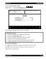
Page 285: ...4 F6 F3 F9 F7 Ack Alert Tone F4 F6 F4 F3 F9 Acknowledge Alert Tone F4 F6 F4 F3 Addressing Mode F4 F6 F7 F5 Aff Hold Off sec F4 F4 F2 F2 Affiliation Type F4 F4 F3 Alert Tone Vol Offset db F4 F3 F2 Alert Tones F4 F3 F2 Alias F4 F4 F3 Alt Display Time ms F4 F3 F6 Announcement Group F4 F4 F4 Auto Access Code Select F4 F6 F3 F8 Auto Dial Holdoff ms F4 F4 F2 Auto Light F4 F3 F6 Auto Reset Carr Ovrd F4 F...

Page 286: ...4 F6 F3 F7 Call Alert Operation F4 F4 F4 Call ID F4 F4 F5 Call ID F4 F6 F4 F4 Call ID List F4 F4 F4 Call List F4 F4 F5 Call Text F4 F4 F5 Call Text F4 F6 F4 F4 Carrier Detect Required F4 F3 F5 F8 Channel Assgn Type F4 F4 F3 F9 Channel Assgn Type F4 F6 F3 F9 Channel Bandwidth F4 F4 F3 F9 Channel Change ID F4 F3 F2 Channel Change Id F8 F2 F7 Channel Change Id F8 F3 F5 F9 Channel Delay sec F4 F3 F2 F...

Page 287: ...Talkaround F4 F6 F3 Direct Frequency Enabled F4 F6 F2 Directory Contents F8 F8 Display Light Time sec F4 F3 F6 Display Site Trunking F4 F4 F2 F2 Display Sys Sub F4 F3 F6 Dynamic Priority F4 F3 F5 Dynamic Regrouping F4 F4 F3 E EMERGENCY DATA CONFIGURATION F4 F4 F4 F8 ENHANCEMENT OPTIONS F8 F2 F7 ENVIRONMENT F4 F4 F2 F2 Echo Mute Time ms F4 F6 F3 F6 Emer Limited Patience sec F4 F6 F4 F3 F9 Emer PTT ...

Page 288: ...2 Full Spectrum CC Scan Timer F4 F4 F2 F2 G GE STAR SYSTEM F4 F6 F7 F5 GE STAR System F4 F6 F3 GE Star Signaling F8 F2 F7 GE Star Signaling F8 F3 F5 GET SAVE PROGRAM MENU F3 H HUB Suspends Scan F4 F3 F5 F8 HearClear F4 F4 F3 F9 Hearclear F2 F3 F3 Hearclear F4 F6 F3 F9 Hide ME F2 F2 F7 High Pwr F2 F2 F3 Hot DTMF Timing F4 F4 F3 F9 Hot Keypad F4 F6 F3 Hot Keypad DTMF F4 F4 F4 Hub Defeats PL F4 F6 F2...

Page 289: ...4 MDC Hot Mic Emergency F4 F6 F4 F3 F7 MDC Hot Mic Tx Period sec F4 F6 F4 F3 F7 MDC REPEATER ID F4 F6 F4 F5 MDC SYSTEM OPTIONS F4 F6 F4 F3 F9 MDC SYSTEMS F4 F6 F4 F3 MDC Sel Radio Inhibit F8 F2 F7 MDC Sel Radio Inhibit F8 F3 F5 F9 MDC System F4 F6 F3 MDC System F4 F6 F4 F3 MDC System F4 F6 F4 F3 F7 MDC System F4 F6 F4 F3 F9 MDC Unlimited Calling F4 F6 F3 F7 MERGE FORM F3 F4 MESSAGE TEXT F9 F7 MONI...

Page 290: ...ge F4 F3 F2 Override Timer ms F4 F6 F3 F9 P PERSONALITY MDC OPTIONS F4 F6 F3 F7 PHONE CONFIGURATION F4 F3 F4 PHONE OPTIONS F4 F3 F4 F9 POPUP BACKGROUND F9 F7 PRINT MENU F5 PROGRAM RADIO CODEPLUG F3 F5 F3 F8 PROGRAM RADIO CODEPLUG F3 F5 F4 F8 PROGRAM RADIO CODEPLUG F3 F5 F8 PROGRAM RADIO CODEPLUG F3 F8 PROGRAMMING HISTORY F3 F9 PTT Code Type F4 F6 F3 F9 F7 PTT DTMF Code F4 F6 F3 F9 F7 PTT ID F4 F6 ...

Page 291: ...F4 F9 Proper Code Detect F4 F6 F3 F6 Protocol Type F4 F4 F4 Protocol Type F4 F4 F4 F8 Q QUIK CALL II SYSTEM F4 F6 F7 F4 QUIK CALL II SYSTEM OPTIONS F4 F6 F7 F4 F9 Quik Call II SingleTone F8 F2 F7 Quik Call II SingleTone F8 F3 F5 Quik Key Override F4 F6 F3 F9 Quik Call II System F4 F6 F3 R RAB 1 Code Type F4 F6 F3 F9 F7 RAB 1 DTMF Code F4 F6 F3 F9 F7 RAB 1 MDC Repeater ID F4 F6 F3 F9 F7 RAB 1 Singl...

Page 292: ...Only F4 F6 F3 Remote Monitor F4 F4 F3 Repeater Access F4 F6 F3 F9 F7 Repeater ID F4 F6 F4 F5 Required FLASH Software F8 F3 Reset Type F4 F6 F7 F4 Retry Counter F4 F4 F4 F8 Reverse Burst TOC F4 F6 F3 F9 Revert Announcement Group F4 F4 F4 F8 Revert Fleet ID F4 F4 F4 F8 Revert Individual ID F4 F4 F4 F8 Revert PTT ID F4 F4 F4 F8 Revert Size Code F4 F4 F4 F8 Revert Subfleet F4 F4 F4 F8 Revert Talkgroup...

Page 293: ... Software Path FileName F9 F3 SUBFLEETS F4 F4 F4 F7 Scan Holdoff Strapping F4 F6 F3 F6 Scan List F4 F3 F5 Scan List F4 F4 F4 Scan List F4 F6 F3 Scan Select F4 F6 F3 F6 Scan Type F4 F3 F5 Secondary ID F3 F5 Secondary ID F3 F5 F3 Secondary ID F3 F5 F4 Secondary ID F4 F6 F4 F3 Secure Equipped F4 F3 F2 Secure Punch Thru F4 F3 F2 F6 Secure Clear Strapping F4 F6 F3 F6 Sel Call Reset F4 F6 F4 F3 F9 Selec...

Page 294: ... Alert Decode Feat F8 F2 F7 Stat Alert Decode Feat F8 F3 F5 F9 Stat Alert Encode Feat F8 F2 F7 Stat Alert Encode Feat F8 F3 F5 F9 Status F4 F4 F3 F6 Status F4 F4 F3 F6 Status F4 F4 F4 Status F4 F4 F4 F6 Status F4 F6 F4 F3 Status Alias Number F4 F4 F3 F9 F6 Status Alias Number F4 F6 F9 Status Alias Text F4 F4 F3 F9 F6 Status Alias Text F4 F6 F9 Status Aliasing F4 F4 F3 F9 Status Request F4 F6 F4 F3...

Page 295: ...NU F4 F4 TRUNKING MESSAGE ALIAS F4 F4 F3 F9 F7 TRUNKING PERSONALITY F4 F4 F4 TRUNKING PERSONALITY OPTIONS F4 F4 F4 F9 TRUNKING RADIO WIDE OPTIONS F4 F4 F2 TRUNKING SITE ALIAS F4 F4 F3 F9 F8 TRUNKING STATUS ALIAS F4 F4 F3 F9 F6 TRUNKING SUBFLEETS F4 F4 F4 F7 TRUNKING SYSTEM F4 F4 F3 TRUNKING SYSTEM OPTIONS F4 F4 F3 F9 TRUNKING TALKGROUPS F4 F4 F4 F7 Tactical F4 F4 F4 F8 Talk Permit Tone F4 F4 F4 Ta...

Page 296: ... F3 F6 F6 Tx Freq F4 F4 F4 F6 Tx Freq F4 F4 F4 F7 Tx Inhibit On Busy F4 F6 F3 F7 Tx Period sec F4 F4 F4 F8 Tx Power Leve F4 F6 F3 F9 Tx Power Selec F4 F4 F3 F9 U UNIVERSAL ID F4 F4 F3 Unmute Hold Off ms F4 F6 F7 F5 Unmute Type F4 F6 F3 F7 Unmute Mute Type F4 F6 F3 F9 Upgrades Purchased F8 F3 Upgrades Remaining F8 F3 Upgrading Radio Block F8 F8 F8 V VCO CROSSOVER F2 F2 F7 VCO CROSSOVER F2 F3 F7 VOC...

Page 297: ...n character at a time A start bit precedes each character and a stop bit follows each character Auto Affilliation The ability of radios in a Type II or Type IIi system to automatically transmit their talkgroup and unit ID information to the Central Controller Affilliation occurs after the radio has locked on to the control channel frequency It does not require the radio user to press the PTT Autom...

Page 298: ...the trunked repeater Connect tone is used as a signal to the central controller that a specific voice channel has been assigned There are eight different connect tones available They are 76 60 Hz 83 72 Hz 90 00 Hz 105 88 Hz 116 13 Hz 128 57 Hz 138 46 Hz Continuous The ability of the Motorola trunked system to ensure that a radio just coming into service will Assignment be sent to the appropriate v...

Page 299: ...Only Memory Used by the radio to store its alterable personality data Enter A synonym for the carriage return key Error Any condition that prevents the software from functioning properly or any input response that deviates from what the software was designed to accept ESC The escape key pressing this key returns you to the main menu Exit To leave the current screen and return to the previous scree...

Page 300: ...n mode operation HZ Hertz or cycles per second Increment To increase a value by one unit or step Inverse Video Displaying text on the monitor by using light letters on a dark background MDC 1200 A Motorola proprietary signalling format It is a binary format using 1200 baud minimum shift keying modulation Menu A menu contains a list of functions that can be selected and performed by the RSS user by...

Page 301: ...t is deemed more important to the radio operator than any other The radio is required to always unmute on activity there even though receiving activity on another channel during priority scan Priority Levels A number given to each radio user on a trunked system to allow system access to the most critical users during busy periods Assignment of priority levels is controlled by the System Manager Th...

Page 302: ...5 MHz depending upon the original communications system configuration RIB Radio Interface Box used to connect a computer system to a radio for the purpose of communication between the radio and the computer The RIB consist of level shifting circuits that convert from the standard RSS 232 voltage levels of the computer asynchronous serial interface to the single ended voltage levels present on the ...

Page 303: ...m Talk Permit Tone A programmable brief series of beeps that provides the radio operator with an indication that a voice channel is available and assigned to them Talk Prohibit An audible tone honk heard from the radio s speaker when the PTT is depressed The tone Tone will be heard when either the radio is out of range of the system or the radio is programmed with the incorrect system information ...

Page 304: ...e organization of the RSS The Main menu is considered the trunk and the the functions listed on the screen are considered the branches Tx Transmit Unit ID The electronic tuning alignment information of a particular radio Universal ID A particular personality in a radio unit which is chosen as the one whose trunking identity will always be used to address this unit In this manner a unit would respo...

Reviews: