Installation
2 - 7
Housing Design
Design the engine’s housing so that internal reflections from the aiming and illumination system are not directed
back toward the engine. The reflections from the window or housing can cause problems, and for particular window
tilt angles, these reflections can bounce off the top or bottom of the housing and reach the engine. Also, keep all
housing elements outside the engine clear aperture (see
). Avoid any bright objects around
the engine that can be reflected by a tilted window into the engine field of view and appear in a captured image.
Integrators should be aware of any housing elements within the Engine Stray Light Zone (see
) and follow suggestions for eliminating stray light as outlined on
Recommended Exit Window Information on page 2-14
provides minimum exit window tilt angles. These
dimensional requirements can vary. Consider using baffles or matte-finished dark internal housing colors.
Optical
The SE4750 uses a sophisticated optical system that provides imaging performance that matches or exceeds the
performance of much larger imagers. However, an improperly designed enclosure, or improper selection of window
material, can affect the performance of the SE4750.
Positioning the Exit Window
Position the window so that illumination system light reflected off the inside of the window is not reflected back into
the engine (see
Recommended Exit Window Information on page 2-14
). If the designed enclosure cannot
accommodate the recommended window angle, contact Motorola to discuss positioning requirements. An
improperly positioned window can significantly decrease performance.
Window Positioning Options
There are two options for window positioning:
•
Parallel window - This is the preferred method for imager engines. Adhere to the maximum window distance
specifications in
•
Tilted window - This is used for either laser or imager engines. Adhere to the minimum window tilt
specifications in
.
Avoiding Scratched Windows
Scratches on the window can greatly reduce the performance of the imaging system. Motorola recommends
recessing the window into the housing or applying a scratch resistance coating.
NOTE
Perform an opto-mechanical analysis for the housing design to ensure optimal scanning or imaging
performance.
NOTE
For bar code reading, use either a parallel or tilted window. For document capture applications, Motorola
strongly recommends the parallel window installation. For tilted windows, dust, contamination, and
scratches on the window can cause visible blemishes in the images.
Summary of Contents for SE4750
Page 1: ...SE4750 INTEGRATION GUIDE ...
Page 2: ......
Page 3: ...SE4750 INTEGRATION GUIDE 72E 171726 01 Revision A November 2013 ...
Page 6: ...iv SE4750 Integration Guide ...
Page 10: ...viii SE4750 Integration Guide ...
Page 14: ...xii SE4750 Integration Guide ...
Page 18: ...1 4 SE4750 Integration Guide ...
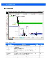
Page 29: ...Installation 2 11 Aiming Pattern Figure 2 6 SE4750 SR LSR AIM Optical Path Aiming Pattern ...
Page 36: ...2 18 SE4750 Integration Guide ...
Page 53: ...Electrical Interface 4 5 Figure 4 3 Parallel Host Flex p n 15 171522 xx ...
Page 66: ...5 12 SE4750 Integration Guide ...
Page 78: ...A 2 SE4750 Integration Guide ...
Page 82: ...Index 4 SE4750 Integration Guide ...
Page 84: ......
Page 85: ......


