


Overview
Camera View
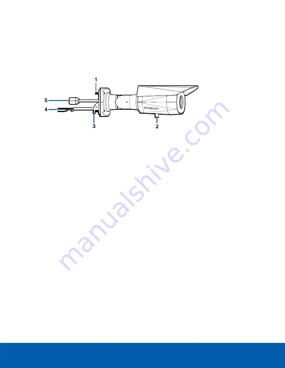
1.
Camera mounting screws
Screws for mounting the camera to the mounting bracket.
2.
Tripod mount
Screw for mounting the camera to the tripod or tilt adjuster.
3.
Mounting hooks
Hooks to attach the camera to the mounting bracket while connecting the required cables.
4.
Power and I/O cables
Cables for connecting the camera to auxiliary power and I/O devices. For more information, see
Connecting to Power and External Devices
5.
Ethernet port
Accepts an Ethernet connection to a network. Server communication and image data transmission
occurs over this connection. Also receives power when it is connected to a network that provides
Power over Ethernet.
Overview
1


