background image

Replacing the Configuration Panel Cover

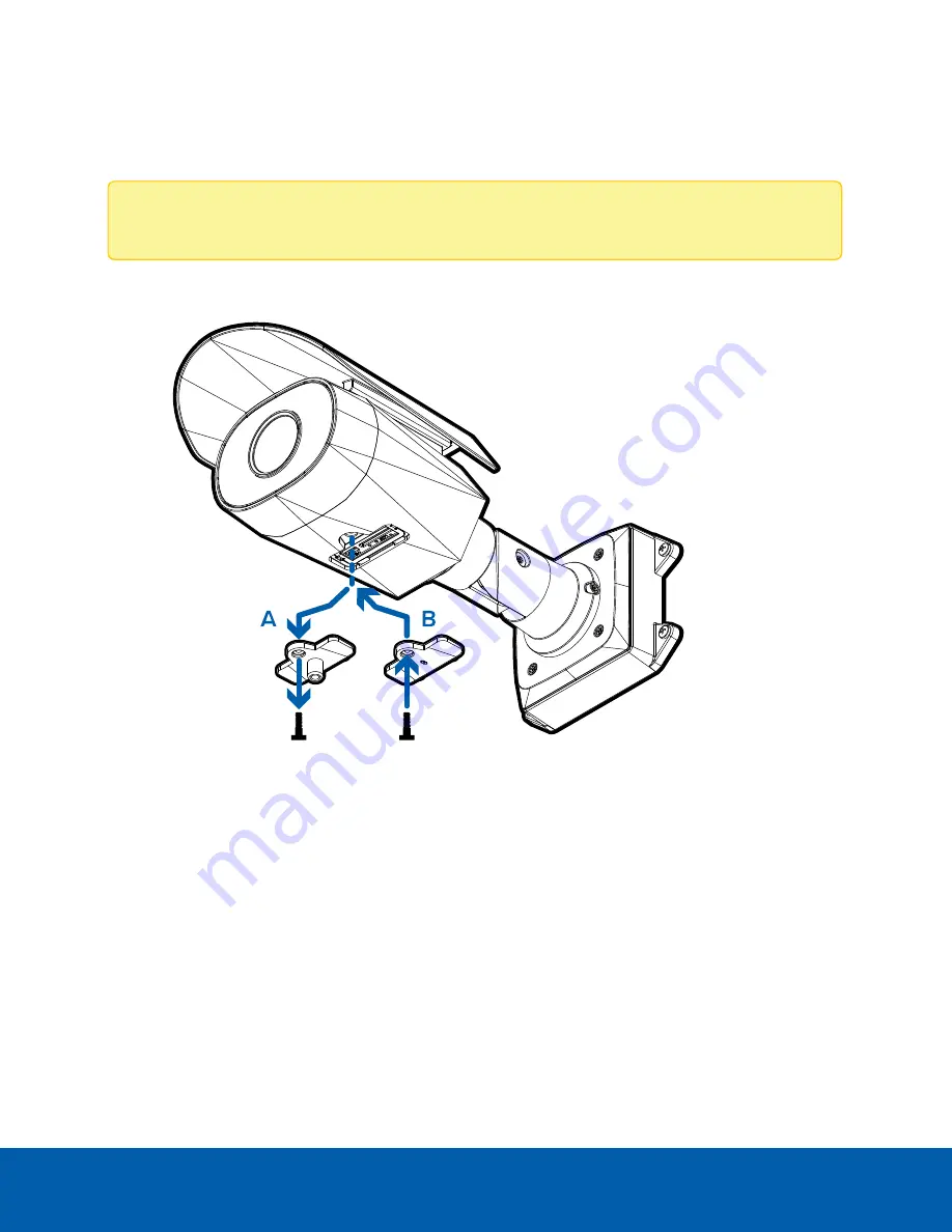
If you are mounting to a wall and do not require the tripod mount, you can replace the configuration panel 
with one that does not include the tripod mount.

Note: 

This step is required for wall mounting the camera.

 1.  Use a T20 Pin-In star-shaped driver to unscrew the configuration panel cover (A). Remove the cover.    

 2.  Use the T20 Pin-In star-shaped driver to screw in the supplied extra configuration panel cover (B).

Aiming the Camera

Reference the camera's live stream as you aim the camera.

 1.  To aim the camera, loosen the adjustment screws on the camera mount arm.

 2.  Rotate and move the camera and mount arm as required. Review the camera’s live video stream to 

help aim the camera correctly.

Aim the camera at the blackbody and screened individual. The camera should be positioned close to 
horizontal and should avoid steep angles.

Replacing the Configuration Panel Cover

17

Summary of Contents for Avigilon H4A-ETD-KIT

Page 1: ...User Guide Avigilon H4 Thermal Elevated Temperature Detection Camera H4A ETD KIT ...

Page 2: ...n trademark patent or other intellectual property rights of Avigilon Corporation or its licensors Disclaimer This document has been compiled and published using product descriptions and specifications available at the time of publication The contents of this document and the specifications of the products discussed herein are subject to change without notice Avigilon Corporation reserves the right...

Page 3: ...s l This product is intended to be supplied by a UL Listed Power Unit marked Class 2 or LPS or Limited Power Source with output rated 12 VDC or 24 VAC 9 W min or Power over Ethernet PoE rated 48 VDC 9 W min l Do not connect directly to mains power for any reason CAUTION Failure to observe the following instructions may result in injury to persons or damage to the device l Do not expose the camera ...

Page 4: ...l Increase the separation between the equipment and the receiver l Connect the equipment into an outlet on a circuit different from that to which the receiver is connected l Consult the dealer or an experienced radio TV technician for help Changes or modifications made to this equipment not expressly approved by Avigilon Corporation or parties authorized by Avigilon Corporation could void the user...

Page 5: ...ared at this time WARNING Do not modify this equipment without the authorization of the manufacturer Disposal and Recycling Information When this product has reached the end of its useful life please dispose of it according to your local environmental laws and guidelines Risk of fire explosion and burns Do not disassemble crush heat above 100 C 212 F or incinerate European Union This symbol means ...

Page 6: ...cting Cables 12 Wall Mount Installation Option 13 Installing the Mounting Bracket 13 Optional Removing the Shroud 14 Reinstalling the Shroud 15 Connecting Cables 15 Mounting the Camera 16 Replacing the Configuration Panel Cover 17 Aiming the Camera 17 Blackbody Installation 18 Connecting to the Camera 20 Initializing a Camera Username and Password 20 Optional Using the USB Wi Fi Adapter 20 Assigni...

Page 7: ... Toggling Degrees Celsius and Fahrenheit 25 Connecting to Power and External Devices 26 Connection Status LED Indicator 28 Maintaining the System 29 Blackbody Maintenance 29 Resetting to Factory Default Settings 30 Setting the IP Address Using the ARP Ping Method 31 For More Information 32 Limited Warranty and Technical Support 33 vii ...

Page 8: ...et while connecting the required cables 4 Power and I O cables Cables for connecting the camera to auxiliary power and I O devices For more information see Connecting to Power and External Devices on page 26 5 Ethernet port Accepts an Ethernet connection to a network Server communication and image data transmission occurs over this connection Also receives power when it is connected to a network t...

Page 9: ...ipod 1 Camera mounts Points for installing the camera to the mounting bracket 2 Mounting hook slots Points to hold the camera to the mounting bracket while connecting the required cables 3 Mounting holes Holes for securing the mounting bracket to the mounting surface Mounting Bracket View 2 ...

Page 10: ...ing to the camera or blackbody 2 Height adjustment knobs x3 Knobs for adjusting and locking the height of the tripod Loosen a knob and slide the tripod to the desired height Tighten the knobs to lock the tripod to the desired height Tripod View 3 ...

Page 11: ...ctor Port for connecting to the included power supply 2 Blackbody front The part of the blackbody that must be directly facing the camera 3 Tripod mount Screw for mounting the camera to the tripod or tilt adjuster Blackbody View 4 ...

Page 12: ... adjustment Move to adjust the angle of the mounted camera or blackbody 3 Tilt lock Loosen to adjust the tilt angle Tighten to lock to the desired angle 4 Bottom tilt adjustment Move to adjust the angle of the mounted camera or blackbody 5 Tripod mount Mounting point for connecting to the tripod Tilt Adjuster View 5 ...

Page 13: ...guration panel cover Covers the configuration panel Showing the configuration panel without the tripod mount For more information on the configuration panel see the Configuration Panel View on the next page Front View 6 ...

Page 14: ... an active connection in the Ethernet port 3 Connection status LED indicator Provides information about device operation For more information see Connection Status LED Indicator on page 28 4 Micro USB port Accepts a micro USB to USB adapter Only required when using the Avigilon USB Wi Fi Adapter Configuration PanelView 7 ...

Page 15: ...ocking mechanism for the mount arm Kit Package Contents l Avigilon H4A Thermal Camera l Spacer for tripod mounting l Panel cover without tripod mount connector l Mounting template sticker l 4 screws and anchors for solid walls l Protective cable boot l T20 Pin In star shaped driver l Blackbody and power supply l Tripod x2 l Tilt adapter for tripod mounts x2 Side View 8 ...

Page 16: ...indoor environments with a stable ambient temperature between 18 C and 24 C 65 F to 75 F and located in an area that is not subject to air drafts from radiator or HVAC systems l Install the solution with a neutral backdrop behind the target subject The camera s field of view should not be directed towards outdoor entrance or exit points and should not include thermally reflective surfaces or stron...

Page 17: ... look directly into the camera l Make sure that the blackbody and face of the person are clearly visible in the camera s field of view and not at the edge of the frame Preparing Individuals for Screening The elevated temperature detection solution can only be used for screening one person at a time for elevated skin temperature l Ensure the person is acclimated to the indoor environment before ste...

Page 18: ... the tripod legs and use the height adjustment knobs to set the to 1 5m to 2m 5 ft 6 5 ft 2 Remove the taped spacer from the underside of the camera 3 Screw the camera onto the tripod mount with the spacer positioned in between B Optionally you can screw the tilt adjuster onto the tripod and then screw the camera onto the tilt adjuster with the spacer positioned in between A Adjust the tilt to ens...

Page 19: ... camera s digital I O connector cables For more information see Connecting to Power and External Devices on page 26 2 If an external microphone and or speakers need to be connected to the camera connect the devices to the camera s audio I O cables For more information see Connecting to Power and External Devices on page 26 3 Connect a network cable to the Ethernet port RJ 45 connector The Link LED...

Page 20: ...ee Connection Status LED Indicator on page 28 Wall Mount Installation Option For a more permanent and less obtrusive thermal camera installation you can mount the camera to a wall so that it is positioned in front of the elevated temperature detection subject and the blackbody For more information see Installation Guidelines on page 9 Installing the Mounting Bracket If the cables for the camera wi...

Page 21: ...cket or junction box to prevent moisture from entering the mounting surface 4 Insert the mounting hooks on the rear of the camera into the mounting hook slots on the mounting bracket then let the camera hang Optional Removing the Shroud The shroud should only be removed when the camera is installed indoors and space is limited 1 As you press down on the center of the shroud pull up the corners of ...

Page 22: ...era connect the devices to the camera s audio I O cables For more information see Connecting to Power and External Devices on page 26 3 Install the protective cable boot You may choose to skip this step if you are using the optional junction box a Remove the protective cable boot that is preinstalled over the Ethernet port then thread one end of the Ethernet cable through it Ensure the orientation...

Page 23: ...inguish the auxiliary power cable it is labeled AUX PWR and has a thicker gauge 6 Check that the Connection Status LED indicator indicates the correct state For more information see Connection Status LED Indicator on page 28 Mounting the Camera Once all the cable connections have been made secure the camera to the mounting bracket 1 Tuck the extra lengths of cables into the cable entry hole 2 Secu...

Page 24: ... Use the T20 Pin In star shaped driver to screw in the supplied extra configuration panel cover B Aiming the Camera Reference the camera s live stream as you aim the camera 1 To aim the camera loosen the adjustment screws on the camera mount arm 2 Rotate and move the camera and mount arm as required Review the camera s live video stream to help aim the camera correctly Aim the camera at the blackb...

Page 25: ...d position and height of the blackbody Blackbody devices are shipped to be calibrated for 35 C 95 F and ready to be used with the camera No further calibration is required 1 Open the tripod legs and use the height adjustment knobs to set the to 1 5m to 2m 5 ft 6 5 ft 2 Screw the blackbody onto the tripod mount B Optionally you can screw the tilt adjuster onto the tripod and then screw the blackbod...

Page 26: ... supply to the blackbody Wait 5 minutes for the blackbody to power up Verify the LED on the blackbody is on and not blinking 5 Position tripod and blackbody so the front of the blackbody is directly facing the thermal camera For more information see Blackbody View on page 4 Blackbody Installation 19 ...

Page 27: ...pter when connecting a camera in the factory default state you will be redirected to the Create Administrator User page to create the first user For more information see Avigilon USB Wi Fi Adapter System User Guide l Avigilon Control Center software when connecting a camera in the factory default state the client software will ask you to create a new user For more information see the Avigilon Cont...

Page 28: ...e You must create a user with administrator privileges before the camera is operational For more information see Initializing a Camera Username and Password on the previous page l Cameras manufactured before January 1 2020 login to the camera using the default username of administrator with no password It is recommended that you change the password after your first login Optional Configuring SD Ca...

Page 29: ...dy temperature area in the image The blackbody ROI must be placed completely within the gray area of the blackbody and should not have any portion outside of that area Note If the blackbody position or camera angle is changed at all after setting the blackbody ROI the placement of the blackbody ROI will have to be updated for that change 4 Click Apply to save your settings Verifying the Temperatur...

Page 30: ...he ACC Client Compare this temperature reading with the temperature reading obtained of the subject in step 2 If these two temperatures match no further actions are required 5 If the two temperatures readings are different calculate the difference This number will be your temperature offset For example if the manually obtained temperature reading is 98 6 F and the ACC Client temperature reading is...

Page 31: ... Threshold C or F The threshold above which a person may need further screening Default is the calibrated value from the thermal camera If an elevated temperature at or above the threshold is detected and a red bounding box are displayed over the face in the live video l Lower Temperature Threshold C or F The threshold below which a person may need further screening Default is the calibrated value...

Page 32: ...d value from the thermal camera Any temperature detection below this threshold will trigger the event l If Object with expected temperature is selected configure both the lower and elevated temperature thresholds Any temperature detection that falls between the specified thresholds is considered within the acceptable range and will trigger the event When a detected temperature matches the threshol...

Page 33: ...he two power wires to the brown and blue auxiliary power wires The connection can be made with either polarity WARNING This product is intended to be supplied by a UL Listed Power Unit marked Class 2 or LPS or Limited Power Source with output rated 12 VDC or 24 VAC 9 W min or Power over Ethernet PoE rated 48 VDC 9 W min Power supplies and external devices are connected to the camera through the po...

Page 34: ... 6 Pink Digital Output 7 Purple Reserved Wire do not connect 8 White Reserved Wire do not connect l Relay l Switch l M Microphone l S Speaker l AUX1 Brown Auxiliary Power Wire labeled AUX PWR l AUX2 Blue Auxiliary Power Wire Connecting to Power and ExternalDevices 27 ...

Page 35: ...tempting to obtain an IP address Discoverable Two short flashes every second Obtained an IP address but not connected to the Network Video Management software Upgrading Firmware Two short flashes and one long flash every second Updating the firmware Connected On Connected to the Network Video Management software or an ACC Server The default connected setting can be changed to Off using the camera ...

Page 36: ... and testing every 2 years to have the device s certification maintained Please contact Avigilon to arrange sending your device for calibration after 2 years Warranty service and technical support can be obtained by contacting Avigilon Technical Support avigilon com contact Maintaining the System 29 ...

Page 37: ...era will not affect video that has been recorded to the SD card Figure 2 The firmware revert button in the Configuration Panel 1 Ensure the camera is powered on 2 Unscrew the configuration panel cover on the bottom of the camera 3 Using a straightened paperclip or similar tool gently press and hold the firmware revert button for 3 seconds 4 Screw the configuration panel cover back into place CAUTI...

Page 38: ... H4 and H5 IP Camera Web Interface User Guide 1 Locate and make note of the MAC Address MAC listed on the Serial Number Tag for reference 2 Open a Command Prompt window and enter the following commands a arp s New Camera IP Address Camera MAC Address For example arp s 192 168 1 10 00 18 85 12 45 78 b ping l 123 t New Camera IP Address For example ping l 123 t 192 168 1 10 3 Reboot the camera 4 Clo...

Page 39: ...ilon Control Center Client User Guide l Web Interface User Guide Avigilon High Definition H4 and H5 IP Cameras l Avigilon USB Wi Fi Adapter System User Guide l Avigilon Camera Configuration Tool User Guide These guides are available on help avigilon com and on the Avigilon website avigilon com support For More Information 32 ...

Page 40: ...t Avigilon warranty terms for this product are provided at avigilon com warranty Warranty service and technical support can be obtained by contacting Avigilon Technical Support avigilon com contact Limited Warranty and TechnicalSupport 33 ...

Reviews: