background image


Morpheus Technologies Owner’s Manual      


http://www.BaseRigs.com/


Page 9                                                                                                 Morpheus Technologies


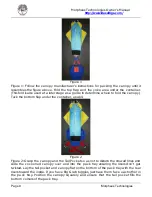
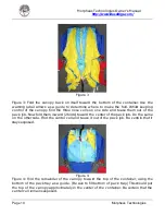
Figure 1 

Figure 1: Follow the canopy manufacturer’s instructions for packing the canopy until it 

resembles the figure above. Fold the top flap and the yoke area under the container. 

(This fold is also used at a later stage as a guide to determine where to fold the canopy.) 

Tuck the bottom flap under the container, as well. 


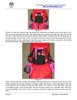
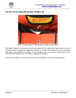
Figure 2 

Figure 2: Grasp the canopy and the Tail Pocket so as not to disturb the stowed lines and 

slide  the cocooned canopy over and into the pack tray ensuring the risers don’t get 

twisted. Lay the tail pocket and canopy flat on the bottom of the pack tray with the rear 

risers toward the inside. If you have Big Grab toggles, just have them face each other in 

the pack tray. Position the canopy squarely and ensure that the tail pocket fills the 

bottom corners of the pack tray. 

Summary of Contents for Gargoyle

Page 1: ...Morpheus Technologies Owner s Manual http www BaseRigs com Page 1 Morpheus Technologies Owner s Manual ...

Page 2: ...rolled instruction in the use of this parachute assembly Do not use this equipment without inspecting it and all of its components thoroughly before each and every use Replace any defective or worn components before use Morpheus Technologies and its affiliates offer no warranty expressed or implied as to the reliability or safety of any equipment or product that it sells This equipment is sold wit...

Page 3: ...oday and it is our promise to you to constantly strive for ways to better our equipment which in turn can help to make our sport safer Therefore it is important to obtain any feedback that may help our company in this effort Please feel free to share any observations suggestions etc No matter how insignificant it may seem we are always open to new ideas and what better place to get them than in th...

Page 4: ...sed as a guideline only It is the responsibility of the user to ensure that his her container is properly assembled maintained packed worn and used It is the user s responsibility to seek out and obtain proper training before using this or any B A S E specific equipment Please read this entire manual before attempting to pack or utilize this equipment in any way If after you have read this manual ...

Page 5: ...9 1 Toggle Attachment Method 1 36 9 2 Toggle Attachment Method 2 37 9 3 Setting your brakes Line Mod No slider 38 40 9 4 Setting your brakes With slider 41 43 10 Pilot chutes and bridle 44 10 1 Jumping hand held 45 47 10 2 Jumping with pilot chute stowed 48 49 11 Safety Checks 50 51 12 Inspecting and Maintaining your equipment 52 12 1 Canopy Check List 52 12 2 Harness Check List 53 12 3 Container ...

Page 6: ... take time to read this manual completely regardless of your experience level You will learn about how to assemble pack and safely use your As well as the great new features of your How to get the most out of your How to take care of your W A R N I N G MORPHEUS TECHNOLOGIES OWNER S MANUAL This manual is not a course of instruction on how to make a parachute jump nor does it contain regulations tha...

Page 7: ...Morpheus Technologies Owner s Manual http www BaseRigs com Page 7 Morpheus Technologies Section 2 Packing the Genesis Velcro container ...

Page 8: ...k The side tuck pockets that keep the shrivel flap bridle in a clean manner for a stowed jump can be teased out and act as a primer for the Velcro for low freefalls Hence the triple function The Genesis container is designed to be very packer friendly and will fit all B A S E specific canopies It features a snag resistant shrivel flap that tucks into the top flap of the container This allows air t...

Page 9: ... fold the canopy Tuck the bottom flap under the container as well Figure 2 Figure 2 Grasp the canopy and the Tail Pocket so as not to disturb the stowed lines and slide the cocooned canopy over and into the pack tray ensuring the risers don t get twisted Lay the tail pocket and canopy flat on the bottom of the pack tray with the rear risers toward the inside If you have Big Grab toggles just have ...

Page 10: ...ne side and tease them out of the pack job Now fold them inward 2 folds toward the center of the pack job Do the same on the other side Find the center cell and tease it out of the pack job Be certain that it stays exposed Figure 4 Figure 4 Fold the remainder of the canopy toward the top of the container using the bottom of the pack tray as a guide Be sure to fill bottom of pack tray This should p...

Page 11: ... and the squared off end is at the bottom of the container where the pilot chute and bridle are stored The bridle should pass to the right side of the top Velcro flap Figure 6 Figure 6 Keeping the canopy tidy grasp either side flap and pull it toward the shrivel flap while working the canopy into the container Align the Velcro of the side flap so that it is even with the tuck portion of the top fl...

Page 12: ...If it does not STOP immediately and inspect the assembly Close the riser covers and tuck the top of the shrivel flap into the tuck at the top of the container Dress the container It helps to put the rig on your back and rock backwards on the floor to compress the pack job Be sure that Velcro is mated properly first Proceed to the pilot chute section and follow instructions according to the type of...

Page 13: ...Morpheus Technologies Owner s Manual http www BaseRigs com Page 13 Morpheus Technologies Section 3 Packing the Gargoyle Twin dual pin container ...

Page 14: ...ucial junctures The Gargoyle Twin can be ordered with Style Stealth or Streamlined Stealth riser covers Through observation and discussions with locals at several popular wingsuit cliff sites we saw a need to improve upon container opening characteristics during wingsuit deployments Hence the development of Dynamic Corners This design allows the tray to open fully leaving no edges for the canopy o...

Page 15: ...o fold the canopy Tuck the bottom flap under the container as well Figure 2 Figure 2 Grasp the canopy and the Tail Pocket so as not to disturb the stowed lines and slide the cocooned canopy over and into the pack tray ensuring the risers don t get twisted Lay the tail pocket and canopy flat on the bottom of the pack tray with the rear risers toward the inside If you have Big Grab toggles just have...

Page 16: ...d the three nose cells on one side and tease them out of the pack job Now fold them inward 2 folds toward the center of the pack job Do the same on the other side Find the center cell and tease it out of the pack job Be certain that it stays exposed Figure 4 Figure 4 Fold the remainder of the canopy toward the top of the container using the bottom of the pack tray as a guide Be sure to fill bottom...

Page 17: ...ght flap Figure 6 Figure 6 Place the pin that is closest to the canopy through the loop Clear the bottom flap from under the container and bring it up over the canopy Feed the pull up cord through the bottom closing loop located on the bottom flap then through the bottom left grommet and finally through the bottom right grommet Ensuring that the bridle is not twisted place the remaining pin pin th...

Page 18: ...e pin shape resembles the arch of a bridge with the end of the pin passing under the right stiffener therefore reducing the risk of the pin being pushed out The bridle should remain straight and not twisted the bridle below the bottom pin should be tucked under the right side flap and then fed in to the bridle protector flap Figure 8 Figure 8 Close the pin protector flap taking care to keep the br...

Page 19: ...iddle of the container in between the two pins rather than out of the top as shown in figure 9 Morpheus Technologies sees no advantage or difference to using this bridle routing It is personal preference to which of these two possibilities you choose Just ensure the instructions for figure 7 regarding pin insertion and the bridle position are always followed Figure 9 Alternative bridle routing ...

Page 20: ...Morpheus Technologies Owner s Manual http www BaseRigs com Page 20 Morpheus Technologies Section 4 Packing the HE or WS X Container ...

Page 21: ... It incorporates many features of the Gargoyle twin such as the no tension pin protector flap This flap is designed to open cleanly and quickly at low airspeeds yet has been thoroughly tested at terminal and withstands the performance of radical freefly manoeuvres It s streamline design and curved yoke contours to the user s body shape and length allowing for maximum comfort and flexibility The ba...

Page 22: ...Figure 2a and 2b Figure 2a 2b At this point you must split the pack job to allow space for the top closing loop to pass through Use the mid rib of the center cell to guide you were to split the pack job Note The top closing loop passes through the grommet of the floor plate held in place by the standard knot and washer The closing loop needs to be approximately 2 3 in length depending on the canop...

Page 23: ...ridle out of the top right corner Insert the pin that is closest to the canopy attachment point through the closing loop Ensure the canopy does not slide in the tray as you close the container Please refer to figure 7 of Section 3 Packing the Gargoyle Twin for details of the correct method to insert the closing pins and route the bridle Figure 4 Figure 4 Fold the tail on top in the normal manner t...

Page 24: ...The WSX or Helium containers can also be packed in the exactly the same manner as the Gargoyle Twin container by using the normal 3 4 closing loop attached to the top flap The small Mylar stiffener provided is then inserted into the pockets either side of the grommet to keep the loop in position as shown in Figure 5 It is recommended to use the normal top flap closing loop on non terminal jumps ...

Page 25: ...on 5 Packing with dynamic corners Figure 1 Figure 1 After closing the top flap the pack job should resemble Figure 1 Figure 2 Figure 2 Fold the Dynamic Corner inward and place this fold along the side of the container between the container sidewall and the folded canopy Repeat for the other side ...

Page 26: ... www BaseRigs com Page 26 Morpheus Technologies Figure 3 Figure 3 Before closing the bottom flap the packjob should resemble the photo Figure 4 Figure 4 Close the bottom flap in the normal way The container should now resemble the photo above ...

Page 27: ...the rig on long hikes The now Razor s Edge is an improved version of the Razor offering even lighter weight with the utilization of low volume foam low profile legpads and riser covers and a type 17 chest strap The Razor utilizes the same field proven pin flap configuration as our Gargoyle line of containers yet with this new design and lack of sidewalls it makes for a much flatter profile allowin...

Page 28: ... Manual http www BaseRigs com Page 28 Morpheus Technologies Figure 1 Packing the Razor is exactly the same as for the Gargoyle Twin up until it s time to drag it to the container see Figure 1 of Section 3 Packing the Gargoyle Twin ...

Page 29: ...ed Lay the tail pocket and canopy flat on the bottom of the pack tray with the rear risers toward the inside If you have Big Grab toggles just have them face each other in the pack tray Position the canopy squarely and ensure that the tail pocket fills the bottom comes just short of the bottom of the pack tray See figure 2a 2b and figure 3 of Section 4 Packing the HE or WS X Or for traditional clo...

Page 30: ...Morpheus Technologies Owner s Manual http www BaseRigs com Page 30 Morpheus Technologies Figure 4 Figure 4 Close the bottom flap in the normal way The container should now resemble the photo above ...

Page 31: ...tainer Risers with slider down retainer strap Control Toggles Pilot Chute Bridle Hard housings installed Elastics for Leg Chest Straps Release Handle Gargoyle Closing loops Genesis Shrivel Flap Helium WS X treme Dynamic Corners Integrity risers and Mylar stiffener for top flap closing loop closure Razor Integrated Risers Type 17 chest strap ...

Page 32: ... that hard housings are considered safer for use in this application Figure 1 3 Ring Release System Assembly Before assembling the 3 Ring release system be certain that the risers are not twisted or reversed 1 Lay the container face down as you would when packing it Insert the yellow cables into their appropriate hard housings Remember that the long cable is to be inserted into the long housing th...

Page 33: ...the yellow cable through the white loop making certain that the loop is not twisted Be careful not to bend the cable too sharply or kink it Insert the free end of the cable into the channel provided on the back of the riser Section 8 1 Slider down retainer strap The slider down retainer strap is situated on the front left riser To use the strap simply release the strap from the popper as shown in ...

Page 34: ...o control lines each cascade into five Once you have orientated the lines properly on the 5 links inspect them Finger tighten all 4 connector links Then apply a 1 4 turn with a 9mm wrench Do not over tighten as this can strip or crack the link and cause it to fail Slide the slider bumpers covers over the links Note The slider retainer strap is attached to the left front riser this strap is used to...

Page 35: ...t threaded through the riser guide ring Figure 1 Figure 1 Make a half hitch knot at the desired point along the brake line use a magic marker to make a mark on the line Figure 2a and 2b Figure 2 Make a loop of brake line above the knot and thread it through the FRONT SIDE of the toggle as shown in figure 2a Then pass the loop over the BOTTOM of the toggle as shown in figure 2b Figure 3 Figure 3 Pu...

Page 36: ...installed toggle attachment loops Figure 1 Figure 1 Pass the control line through the toggle s grommet from the Velcro side of the toggle Figure 2 Figure 2 Then thread the bottom of the toggle through the toggle attachment loop pulling the slack brake line back through the grommet Figure 3 Figure 3 The assembled toggle should look like photo above ...

Page 37: ...ne continuity and make sure that when the brakes are unstowed the control lines run straight from the toggle your hand to the trailing edge of the canopy without passing through anything else The top of the toggle must never pass through the guide ring Figure 1 Figure 1 Determine which brake setting will be used and place the white loop on the riser through the cat s eye loop on the control line ...

Page 38: ...e 2 Then pass the white riser loop through the riser guide ring when using the line mod the control line DOES NOT pass through the guide ring Figure 3a and 3b Figure 3 Put the top of the toggle through the white loop on the riser and stow the top of the toggle in the elastic keeper provided on the riser ...

Page 39: ... the riser and around to the elastic keeper located on the front side of the rear riser Check proper routing Be certain that the control line leading to the canopy is routed to the outside Figure 5 Figure 5 Be certain that the Velcro on the toggle mates with the Velcro on the riser Also make certain that the top of the toggle does not pass through the guide ring ...

Page 40: ...ve the proper set up for jumping with a slider The control lines MUST pass through the riser guide rings and the appropriate slider grommets The top of the toggle must never pass through the guide ring Figure 1a and 1b Figure 1 Pull the toggle down so that the appropriate cat s eye is below the guide ring When jumping slider up this is typically the brake loop closest to the toggle ...

Page 41: ...riser The white riser loop is not utilized when a slider is being used Just lay it to the side Figure 3 Figure 3 S fold and stow the excess control lone to the inside of the riser and around to the elastic keeper located on the front side of the rear riser Check proper routing Be certain that the control line leading to the canopy is routed to the outside Be certain that the Velcro on the toggle m...

Page 42: ...eRigs com Page 42 Morpheus Technologies Figure 4 Figure 4 This is how it should look when finished Be certain that the top of the toggle is through the appropriate cat s eye only and that it does not pass through the white riser loop or the guide ring ...

Page 43: ...el flap to the canopy the loop that exits the rounded end of the shrivel flap bridle is lark s headed to the canopy Make sure that the rounded end of the shrivel flap extends to the canopy The larger loop on the other end of the bridle furthest from shrivel flap is larks headed to the pilot chute To do this pass the bridle loop through the bridle attachment point making sure that bridle goes throu...

Page 44: ...gure 1 After packing your container put it on as normal Make all harness adjustments and stow all the excess webbing Grasp the bridle with your right hand Make certain that the bridle runs from shrivel flap bottom pin directly to your hand without passing around or through anything that could cause a pilot chute in tow malfunction ...

Page 45: ...e to full arm extension S fold the remainder of the bridle into your hand using approximately 6 folds working your way toward the pilot chute When finished the pilot chute should be hanging by the bridle attachment point Drag the pilot chute through the air causing it to inflate and then let it rest If the pilot chute does not inflate STOP Do not continue Inspect your pilot chute ...

Page 46: ... and 3b Figure 3a and 3b Continue S folding the mesh into the right hand and then continue to S fold the pilot chute into your hand The centreline of the pilot chute should stay elongated throughout the entire procedure Note The larks head knot can be placed in a fold to reduce the bulk in the hand ...

Page 47: ...pheus Technologies Figure 4 Figure 4 Extend the arm to check bridle length and routing It is VERY IMPORTANT to ensure that the bridle exits over the hand between the thumb and forefinger Otherwise the bridle could wrap around your arm and cause a hesitation or malfunction ...

Page 48: ...e mesh and slide your hand toward the pilot chute fabric stopping at the seam between the mesh and the fabric Flip the pilot chute so that it resembles a mushroom shape with the disk handle at the top Figure 2 Figure 2 Whilst keeping this shape use the other hand to S fold the mesh into your hand making approximately 6 8 folds Make certain that the bridle attachment point faces towards the disc ha...

Page 49: ...The bridle attachment point and the start and finish of each S fold should be incorporated in the disc handle area This makes for a good grip at pull time The length of the pilot chute should be approximately the same length as the BOC pilot chute pocket Figure 4 Figure 4 Place the excess bridle in the pouch This slack helps the pilot chute extend from the pocket without tension Place the pilot ch...

Page 50: ...strap for proper threading and be certain that any excess webbing is stowed See illustration bellow for proper threading Be sure that the main lift webs are not twisted Check threading of leg straps and tuck away any excess webbing see illustration below for proper threading Moving to the back Medusa Container Velcro Check the Shrivel Flap by tugging gently on the bridle at the bottom of the conta...

Page 51: ...an normal into the bridle protection flap and take extra care when extending the arm to check bridle length Be certain that there is nothing to snag or interfere with the bridle or pilot chute during deployment i e clothing protective gear such as elbow or knee pads etc Your Leap of Faith Whenever we make a parachute jump we rely on a number of things to get us safely to the next jump One of which...

Page 52: ...egrity of the system Also remember that this is a single parachute system so it should be inspected to the airworthiness of a reserve system not a main Section 13 1 Canopy Check List Lines 4 riser groups 2 Sets of Control Lines Cat s eyes Bartacks Line Attachment Tabs 1 7 Cells Bottom 1 7 Cells Inside and crossports 1 7 Cells Top surface Bridle Attachment Point top bottom and internal Stabilizers ...

Page 53: ...luding under the ring covers Look for any broken stitches and or fraying of the webbing Insect the hardware on your harness for any damage burrs rough edges Be sure that the cutaway housing is in tact and free of obstructions Inspect the yellow cutaway cable and be certain that it is free of kinks and periodically clean it with a paper towel and a food grade silicone spray This keeps it moving fre...

Page 54: ...nd bartacks Velcro and elastic Inspect your risers closely Check webbing for any fraying or broken stitching Check for proper routing of three ring assembly page 24 Manoeuvre the rings of the three rings on occasion to make certain they are moving freely Inspect the white Three ring loop This is a highly critical point If there is any damage or wear it must be replaced before the next jump Section...

Page 55: ...tend to take a lot of abuse Although the pilot chute itself can be pretty low maintenance component it must be inspected regularly as it is the first thing out during deployment and the last thing in when packing They can sometimes get dragged along the ground after landing or get snagged on bushes or limbs Although we use Zero P fabric and it is very durable it is still subject to tears and holes...

Page 56: ... end of the bridle Check for any wear or loose or broken stitching If you own a pin closed container check the stitching on the webbing that attaches the curved pins to the bridle If it becomes damaged in any way be sure to have it repaired Make sure that the pins are in good condition and free of any damage that could interfere with them being extracted at deployment time ...

Page 57: ...heus Technologies Appendix A Contact details Morpheus Technologies 5107 Lantana Street Zephyrhills FL 33542 813 780 8961 kathy baserigs com http www BaseRigs com Morpheus Technologies are proud to use the following equipment http www basetroll com http www Phoenix Fly com ...

Page 58: ...nd Stowed Mesh 800 4 5 No Yes Yes No No No Hand Stowed Mesh 900 4 6 No No Yes Yes No No Stowed Mesh 1100 6 7 No No No Yes No No Stowed Mesh 1500 7 9 No No No Yes Yes Yes Stowed Mesh 2000 9 No No No No Yes Yes Stowed Mesh Note Use of sail is NOT recommended for BASE jumping due to the inconsistent opening speed and unreliable heading performance This chart is to be used as a reference only It is wi...

Page 59: ...ds 138 ft 61 mph 4 seconds 242 ft 72 mph 5 seconds 365 ft 87 mph 6 seconds 500 ft 96 mph 7 seconds 650 ft 103 mph 8 seconds 808 ft 107 mph 9 seconds 971 ft 111 mph 10 seconds 1138 ft 114 mph This chart is to be used as a reference only These numbers can be greatly affected by variables that are specific to the environment in which you are jumping Do not take these speeds and distances as pure fact...

Page 60: ...Grab toggles are made of Type 4 webbing and come standard in Fluorescent Orange They are lightly stiffened with Lolon coated cable to give the loop shape This makes them very easy to see and to grab upon deployment yet they do not get in the way when reaching for rear risers first It is important to be able to grab your toggles without fumbling when a quick response is needed They are easy to pack...

Reviews: