Morpheus Technologies Owner’s Manual
http://www.BaseRigs.com/
Page 35 Morpheus Technologies
Section 10: Toggles and Settings
Section 9.1: Toggle assembly – Method 1; Standard Brake line attachment
procedure
Note: Remember to adjust the toggle attachment point when removing the toggle to
change between slider up and slider down. The length of the brake line increases when
not threaded through the riser guide ring.
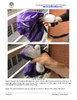
Figure 1
Figure 1: Make a half hitch knot at the desired point along the brake line (use a magic
marker to make a mark on the line).
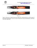
Figure 2a and 2b
Figure 2: Make a loop of brake line above the knot and thread it through the FRONT SIDE
of the toggle as shown in figure 2a Then pass the loop over the BOTTOM of the toggle as
shown in figure 2b.
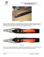
Figure 3
Figure 3: Pull the excess line back through the grommet. The assembled toggle should
look like photo above. (the excess line can be left hanging free, it allows for adjustment
later on)


