Moog Videolarm DeputyDome DDW10CR1 Installation And Operation Instructions Manual Download Page 11

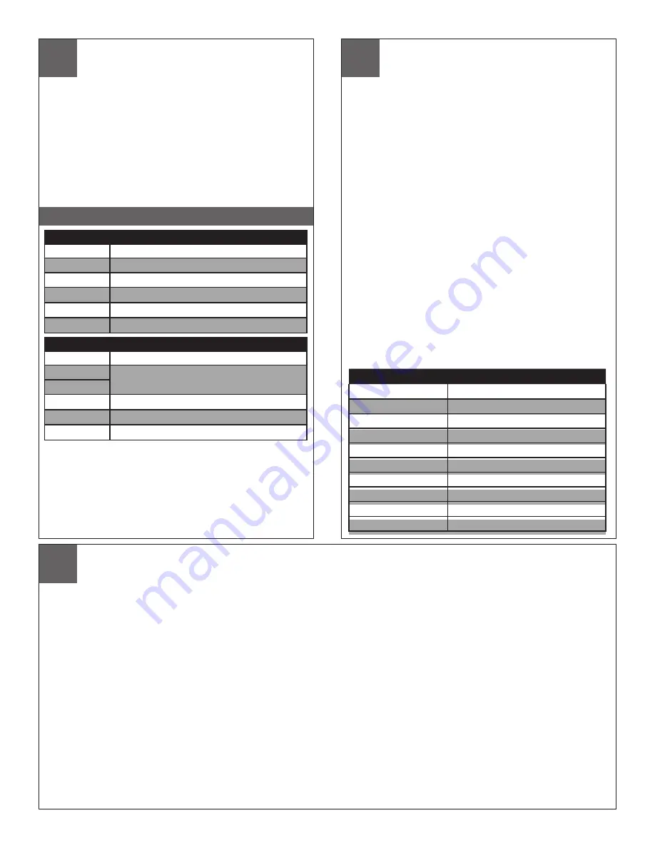
CHART 2 - PARAMETER DIP SWITCH SETTINGS

Switch


Settings

SW6                Address data - On (Closed)

SW5                A4         

SW4                A3         
SW3                A2         

SW2                A1         

SW1                A0         

CONTROL FUNCTIONS


 UNIT PARAMETERS


Alarm  sense,  camera  on-screen  display  and  baud  rate  can  all    be  controlled  by  the 
dipswitches. The alarm sense can be set to accept either contact closures (NO) or contact 
openings (NC) as the alarm condition. The camera on-screen display will show icons on 
the monitor when zoom, focus, and iris are used. Factory presets are contact closures 
for the alarm sense, "off" for the camera on-screen display, and 9600 baud. To change 
parameters, power down the unit, remove the pan/tilt from the housing, and set the desired 
parameter using switches 1 and 2 as directed in chart 2 below. Replace the unit and power 
up. In UTC mode there is nothing further to do. However, if you're operating in 485 mode 
you must reset the address AFTER POWERING BACK UP following the instructions above.

Switch


Settings

SW6                Parameters - Off (open)

SW5                       

SW4                         
SW3                BAUD RATE: On-9600 Off-4800           

SW2                ALARM:  On - NC      Off - NO         

SW1                DISPLAY:  On - Display on     Off - Display off                 


Zoom, Focus and Iris

Using the manual focus commands leaves the unit in manual focus mode.  
Using the manual iris commands will leave the unit in manual iris mode as 
well.  Zooming the camera will restore the camera to auto-focus and auto-iris.  
Goto preset 89 will also restore auto-focus and auto-iris.

Protocols

The DeputyDome is commanded electrically via RS-485 4-wire protocol.  The 
transmitter is disabled when not in use to allow multiple camera systems to 
be tied to the same response pair. 
 
Control protocols supported are VL-422 (detailed in the Appendix) and Pelco-
P and Pelco-D.  The DeputyDome will automatically sense which protocol is 
being used and respond to it.  Baud rates of  9600 (factory default) and 4800 
are available.  See the Unit Parameters section above for instructions on 
setting the baud rate.

Presets

The DeputyDome has 64 presets that can be used individually or as part of 
an autotour.  To program a preset, set the pan, tilt, zoom, focus and backlight 
compensation settings to the desired value.  Issue the command to store/
program the preset number using an appropriate controller.  (See the Ap-
pendix)   When the Goto Preset number command is given, the system will 
move to the stored pan, tilt, zoom, focus and backlight settings at the highest 
available speed.

                   Autotour

Preset Number                         

Function

79

Record/Run Pattern 2

80

Record/Run Pattern 1

81

Stop Recording Pattern (1 or 2)

84

Reset the Camera System

85

Backlight Compensation On

86

Backlight Compensation Off

87

Night Mode

88

Day Mode

89

Auto Iris / Auto Day/Night

99

Clear All Presets

NOTE:


Erasing  the  EEPROM  will  override  the  other  switch  settings. 
If the EEPROM is erased, power the unit off, set the switches to the desired 
baudrate, alarm position and display mode , with SW4 and SW5 ON and SW6 
OFF, then power the unit on again.  Finally power the unit off, set the address 
and make sure that SW6 is ON, power the unit on and begin normal operation. 

On 


Off


- No Operation 

  - Erase EEPROM

On 


Off

The Autotour function causes the camera to automatically go, in sequence, to each preset that has been programmed into the PTZ. The dwell time at each preset position can 
be individually set to be from 0 to 99 seconds.  See the Menu Driven Settings section to learn how to set dwell time.  The Autotour will continue until a pan or tilt command is 
given.  If the unit loses power while in Autotour, Autotour will be resumed when power is restored.

Pattern


The DeputyDome allows recording of two patterns with each pattern being up to 2 minutes in length. 

This is a separate feature from Autotour.

To record a pattern:
 

1. If the camera is in autotour, use the joystick to stop it.


2. Clear all customized presets such as preset 1, 2, 3 etc. (Note: Once the pattern has been recorded, the presets can be set again) 


3. Set preset 80 (8->0->#->Set) to begin recording pattern 1 (or set preset 79 to begin recording pattern 2)


4.  Use joystick to move the camera (the movement is recorded)


5.  Set preset 81 (8->1->#->Set) to stop recording (for Pattern 1 or 2)

To run a pattern:
 

1. If the camera is in autotour, use the joystick to stop it.


2.  Go to preset 80 (8->0->Set) to run Pattern 1 (or go to preset 79 to run Pattern 2)

To stop a pattern:
 

Move the joystick

Note:

  1. Pattern and Autotour are different processes.  Make sure to use joystick to stop one before initiating another.


2.  In case there is a power outage, the camera would go to Home position after the power is recovered.


3.  To erase a recorded pattern, just record a new pattern and the old one will be automatically erased.

Additional Functions

Additional functions are available using Goto Preset above the normal preset range.  The table below describes these functions.

23

24

25

Summary of Contents for DeputyDome DDW10CR1

Page 1: ...Bullet Resistant Outdoor dome PTZ Camera System with 26x Day Night Camera onboard receiver driver 120Vac heater Tough enough to stop a 9mm bullet PDDW10CR1 Pressurized Version DeputyDome Series 10 ga...

Page 2: ...onents can be damaged if improperly handled or dropped If an item appears to have been damaged in shipment replace it properly in its carton and notify the shipper Be sure to save 1 The shipping carto...

Page 3: ...pect to any Product requiring service during the warranty period which is subjected to any of the following abuse improper use negligence accident lightning damage or other acts of God i e hurricanes...

Page 4: ...bturateur lectronique 22 tapes DDW10CR1 N 115 VAC 90 VA 0 8 Amps DDW10CR2 N 24 VAC Kategorie 2 90 VA 3 75Amps KAMERA SPEZIFIKATIONEN Entschlie ung 470 TVL NTSC 460TVL PAL Minimale Ablichtung 1 0 1 0 L...

Page 5: ...gire a carca a no sentido hor rio para remover a carca a da montagem A montagem da parede pode agora ser unida parede Allenti tutti i dadi della flangia e giri l alloggiamento in senso orario per rimu...

Page 6: ...de r cepteur PDDW10CR2 Verdrahtung f r unter Druck gesetztes Empf ngermodell PDDW10CR2 Fia o para o modelo pressurizado do receptor PDDW10CR2 Collegamenti per il modello pressurizzato della ricevente...

Page 7: ...ur supprimer Pan Tilt rmove montage du d me et doublure So entfernen Sie Pan Tilt rmove Montage der Kuppel und Linienkonferenzen Para remover Pan Tilt rmove montagem da c pula e forro Per rimuovere Pa...

Page 8: ...inserire e installare cupola O Ring Align If Lanyard attaches to both trim ring and the outside of the housing Si Lanyard concede a ambos y el anillo exterior de la vivienda Si Lanyard attache la fois...

Page 9: ...ponga il mandrino dell aria sulla valvola del carro armato e cominci a riempirsi fino a che la valvola limitatrice della pressione non si apra Open the relief valve Drain all air from the housing and...

Page 10: ...G SETTINGS FOR RECEIVER DRIVER UNITS DIPSWITCHES The dipswitches serve a dual purpose First they control the address of the pan tilt when operated via RS485 Second they control the alarm and display f...

Page 11: ...n tilt zoom focus and backlight settings at the highest available speed Autotour Preset Number Function 79 Record Run Pattern 2 80 Record Run Pattern 1 81 Stop Recording Pattern 1 or 2 84 Reset the Ca...

Page 12: ...40 92 WSTH02 8 Star washer 5 41 30 VL1411 DDWC10 P T bracket 1 Part Number Description Qty 42 60 1414 DDWC10 pan limits collars 2 43 92 WSFL01 1 4 Flat washer SS 4 44 92 WSSL01 1 4 Split lockwasher SS...

Page 13: ...40 39 38 37 36 35 57 56 55 54 53 67 66 65 64 63 62 61 60 59 58 70 69 68 79 78 77 76 75 52 51 50 49 48 47 46 45 44 43 42 41...

Page 14: ...later than 20ms after the last byte of the message has been received If the message is not understood by the DeputyDome a NACK message will be sent If an inquiry message is successfully received from...

Page 15: ...s Assignment Message This six byte command sets the address of the dome The address is in hexadecimal and is contained in bytes 4 and 5 If the address is set to FFH then the unit derives its address f...

Page 16: ...t 01 and byte number five is the message terminator byte FUNCTION Byte 3 Byte 4 DESCRIPTION REQUEST POSITION P Get position ASCII character upper case p followed by the character The response to this...

Page 17: ...on data 9 F0 LS nibble 30H 3FH Position data is 30H ored with data nibble F03 F02 F01 F00 of lens focus position data 10 Terminator and Checksum 80H 8FH Most significant nibble is always 8 Least signi...

Page 18: ...he camera commands control parameters of camera operation All the Camera commands generate a Latch Status response message FUNCTION Byte 3 Byte 4 DESCRIPTION MANUAL IRIS TOGGLE L M Toggles iris operat...

Page 19: ...n in the table below BYTE DATA DESCRIPTION 1 F8H Autobaud character 2 Address in hex Camera address 01H DFH 3 S Upper case S 4 P1 MS nibble 30H 3FH Pressure data is 30H ored with data nibble P07 P06 P...

Page 20: ...ousings Poles Power Supplies and Accessories and 5 Years on camera systems SView QView Warriors and InfraRed Illuminators Register Your ProductsOnline Take a few moments and validate your purchase via...

Reviews: