background image

XG0222

28

Installation

Fuel Type

Verify that your fireplace is compatible with your available gas type. 

Natural Gas or Propane shown by "N" or "L" in your model number on 

rating plate. See instructions on converting to propane.

Gas Pressure

Optimum appliance performance requires proper input pressures.
Gas line sizing requirements will be determined in ANSI Z221.3 National 

Fuel Gas Code in the USA and CAN/CGA B149 in Canada.

Pressure requirements (during operation):

The manifold outlet pressure is set from the factory to the appropriate 

pressure but should be verified.
To check pressures, use a manometer and a 1/8” rubber hose attached 

to the inlet or manifold valve ports.

Only install gas shut-off valves approved for use by the state, province, 

or other governing body in which the fireplace is being installed.

Gas Connection

Flexible gas connectors must not exceed 3 feet in length, unless allowable 

within local regulations.

Connect incoming gas line to the 1/2" Male NPT gas inlet.

Purge all air out of gas line before connecting port.

Check  appliance  connection,  valve  and  valve  train  under  normal 

operating pressure with a commercially available leak check solution.

DO NOT USE A FLAME OF ANY KIND TO TEST FOR LEAKS.

Distinction Pressure Requirements

Model 

Minimum

Maximum

D3615NI

D3615STNI 

D4815NI

D4815STNI 

D7215NI

D7215STNI

5.5" W.C.

=

0.2 PSIG

13.8" W.C.

=

0.5 PSIG

D3615LI

D3615STLI 

D4815LI

D4815STLI 

D7215LI

D7215STLI

11" W.C.

=

0.4 PSIG

13.8" W.C.

=

0.5 PSIG

Section 5: Installing the gas line

After gas line is connected, each appliance connection, valve and 

valve train MUST be checked while under normal operating pressure 

with either a Liquid Solution, or Leak Detection Device, to locate any 

source of leak. Tighten any areas where bubbling appears or a leak is 

detected until bubbling stops completely or leak is no longer detected. 

DO NOT use a flame of any kind to test for leaks. A fire or explosion 

will occur, causing serious injury, property damage or death.

When pressure testing the fireplace, Gas line, and input system 

follow the appropriate local codes for your area. DO NOT connect the 

fireplace to pressures in excess of 1/2 lb. This will damage the gas 

control valve.

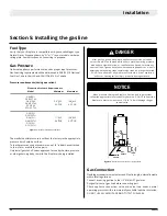
Figure 17. 

 D7215 Pressure Requirements

Figure 18. 

 Gas Inlet Supply location  (Single Sided)

DANGER

NOTICE

1950

76 34 "

432

17"

393

15 12 "

1876

73 78 "

467

18 38 "

1117

44"

356

14"

305

12"

2431

95 11

16 "

2232

87 78 "

203

8"

243

9 9

16 "

127

5"

1096

43 18 "

467

18 38 "

263

10 38 "

432

17"

346

13 58 "

1148

45 3

16 "

1041

41"

155

6 18 "

60

2 38 "

POWER

SUPPLY

GAS

SUPPLY

REVISIONS

REV.

DESCRIPTION

DATE

CHANGED BY

-

.

-

-

ITEM NO. PART NUMBER

DESCRIPTION

QTY.

REVISION

MATERIAL

1

1-2 valve 

handle

1

A

Material <not specified>

2

3-8 to 3-8

Safety Valve

1

A

Material <not specified>

3

BR005-20

Floor Bracket

2

A

20 GA Satin-Coated

4

BR007-20

Glass Bracket

2

C

20 GA Satin-Coated

5

BR008-20

Screen Bar Bracket

9

A

20 GA Satin

6

BR011-10

5" Blanking Disk

4

A

20GA Satin-Coated

7

BR012-20

Gas Valve Bracket

1

B

16 GA Satin

8

BR014-20

Gas Valve Base Bracket

2

B

18 GA Satin

9

BR016-20

DL72 Glass Retainer

16

C

SS/26NP

10

BR017-10

Burner Baffle

1

A

18 GA Satin-Coated

11

BR018-20

Screen Bracket

3

A

20 GA Satin

12

BR030-20

Vertical Door Spring Retainer

4

D

14 GA Satin

13

BR031-20

Vertical Door Spring Retainer/Stop

4

D

14 GA Satin

14

BR033-20

Door Latch

8

D

14 GA Satin

15

BR034-20

Back Door Latch

8

B

14 GA Satin

16

BR035-20

Back Door Spring Retainer/Stop

8

B

14 GA Satin

17

BR044-20

Back Door Navigation Bracket 

2

A

20 GA Satin

18

BR045-20

L & R Side Cover

2

F

20 GA Satin

19

BR046-10

Outtake Divider Bracket

1

A

20 GA Satin

20

BR047-20

Control Drawer Slide

1

C

20 GA Satin-Coated

21

BR048-20

Drawer Slide Bracket

2

C

20 GA Satin

22

BR050-20

Door Side Bracket

2

D

20 GA Satin

23

BR053-20

Upper Brace

2

F

18 GA Satin

24

BR054-20

Air Intake Box Brace

2

E

18 GA Satin

25

BR055-10

Left & Right Spacer

4

D

20 GA Satin

26

BR056-10

Firebox Bottom Support

1

D

18 GA Satin

27

BR057-20

Firebox Bottom Side Support.

2

D

16 GA Satin

28

BR058-20

Burner Mounting Bracket Right

1

A

18 Ga Satin

29

BR059-20

Burner Mounting Bracket Left

1

A

18 GA Satin-Coated

30

BR062-20

Bottom Window Bracket Holder

6

A

20 GA Satin

31

BR063-20

Lower Brace

8

B

18 GA Satin

32

COLL073-20

14" INTAKE COLLAR

4

A

22Ga. SATIN

33

DL63044-10

Service Door

1

B

20 GA Satin

34

DL63193-20

Fan Bracket

3

C

20 GA Satin

35

DL72-Gasket

DL72 Door Gasket - 185" (IN1197)

1

A

IN1197

36

DL72-Gasket2

DL72-LED Glass Gasket - 132"

1

A

IN1197

37

DL72-Gasket4

DL72 Back Door Gasket - 185"

1

A

IN1197

38

DL72001-20

Media Tray Front Left

1

B

20 GA Satin

39

DL72002-20

Media Tray Back Left

1

B

20 GA Satin

40

DL72003-20

Firebox Foot

2

H

20 GA Satin

41

DL72004-20

Firebox Outtake Divider

1

G

20 GA Satin

42

DL72005-20

Firebox Bottom

1

J

20 GA Satin

43

DL72007-20

Back Burner Tray Rail

1

I

20 GA Satin

44

DL72008-20

Media Tray Back Right

1

D

20 GA Satin

45

DL72009-20

Media Tray Front Right

1

D

20 GA Satin

46

DL72011-20

Front Burner Tray Rail

1

B

20 GA Satin

47

DL72012-20

Media Burner

1

B

16 GA Aluminized steel

48

DL72013-20

Base Media Burner

1

B

16 GA Aluminized steel

49

DL72014-20

Firebox Top

1

J

20 GA Satin

50

DL72017-20

Bottom Side Transition Box

2

D

20 GA Satin

51

DL72018-10

Air Intake Box Cover

1

D

16 GA Satin

52

DL72019-20

Light Tray Glass Retainer

2

B

18 GA Satin

53

DL72020-20

Short Light Tray Glass Retainer

2

A

18GA Satin

54

DL72021-20

Top Side Transition Box

2

B

20 GA Satin

55

DL72025-20

Light Tray

1

E

SS/20NP

56

DL72027-10

Rock Tray

2

E

188CRSPERF/20

57

DL72028-10

Rock Tray

2

D

188CRSPERF/20

58

DL72031-20

Air Intake Box

1

C

20 GA Satin

59

DL72032-20

PILOT COVER

1

A

SS/16P

60

DL72033-20

DL72 Door

1

B

14 GA Satin

61

DL72034-20

DL72 Short Door Stiffener

4

C

16 GA Satin

62

DL72035-20

DL72 Long Door Stiffener

4

C

16 GA Satin

63

DL72037-20

Light cover Bracket

1

F

22 GA Satin

64

DL72049-10

Light Cover Side

2

B

22 GA Satin

65

DL72050-10

Light Cover

3

B

22 GA Satin

66

DL72051-20

DL72 Back Door

1

C

14 GA Satin

67

DL72053-20

Side Glass Bracket

2

E

20 GA Satin

68

DL72061

Safety Screen DL72

1

C

Safety InvisiMesh / Steel Frame

69

DL72062-20

5" Pipe

1

A

22 GA Satin

70

DL72063-20

Butt Seam

1

A

22 GA Satin

71

DL72065-20

L-Sidewall Spacer and Handle 

Bracket

2

B

16 GA Satin

72

DL72068-20

Valve Cover

2

A

20 GA Galv. 1/8 Holes

73

DL72071-20

Screen Support Bar

1

A

20 GA Satin

74

DL72072-20

R-Sidewall Spacer and Handle 

Bracket

2

B

16 GA Satin

75

DL72073-10

Back Door Plate

1

B

16 GA Satin

76

DL72076-20

Back Door Glass Bracket

1

B

20 GA Satin

77

DL72077-20

Outer Shell Bottom

1

D

20 GA Satin

78

DL72078-20

Outer Shell Bottom

1

D

20 GA Satin

79

DL72080-20

Outer Shell Side Right

1

E

20 GA Satin

80

DL72081-20

Outer Shell Side Left

1

G

20 GA Satin

81

DL72082-20

Outer Shell Back Wall

4

D

20 GA Satin

82

DL72083-10

Outer Shell Back Wall Strip

3

B

20 GA Satin

83

DL72084-20

Outer Shell Back Wall Air Channel

4

C

20 GA Satin

84

DL72085-20

Outer Front Top Shell

1

C

20 GA Satin

85

DL72086-20

Outer Shell Long Front Top

2

D

20 GA Satin

86

DL72087-20

Outer Shell Short Front Top

2

D

20 GA Satin

87

DL72088-20

Outer Shell Long Front Right

1

E

20 GA Satin

88

DL72089-20

Outer Shell Short Panel Bracket

5

D

20 GA Satin

89

DL72090-20

Outer Shell Long Front Left

1

E

20 GA Satin

90

DL72091-20

Outer Top Window Bracket

1

D

20 GA Satin

91

DL72092-20

DL72-Top Front Frame Edge

1

B

20 GA Satin

92

DL72094-20

Left Side Window Frame

1

B

20 GA Satin

93

DL72095-20

Right Side Window Frame

1

B

20 GA Satin

94

DL72096-20

Outer Bottom Window Bracket

1

C

20 GA Satin

95

EBOX491

PO BOX OUTER COVER

1

C

22 Ga Satin

96

EBOX492

PO BOX INNER COVER

1

B

20 Ga Satin

97

EC1220

CLAMP CONNECTOR, 1/2", SL20C20

1

B

98

EC1466

Fan L/H

3

A

Material <not specified>

99

EC1467

Aluminium Spacer

64

A

Aluminium

100

GC3020

4 Batteries Holder.

1

A

Material <not specified>

101

GC3033b

Proflame Valve W?Stepper Motor 

NG

1

A


102

GF1012

1

A

Material <not specified>

103

GF1111

Gas Orifice Mount

1

0

104

GF1114

Shutoff, Valve, 3/8" Flare to 3/8" 

Flare

2

Brass

105

GF2020

GF2020   90d. FORMED VENT. TUBE

1

B

106

GL1119

DL72 Light Tray Glass

1

A

5mm Tempered Glass

107

GL4030

DL72 Window Glass

1

C

Neoceram Glass 5mm

108

GL5111

DL72 Side-Black Ceramic Glass

2

B

4mm Black Ceramic Glass

109

GL5112

DL72 Back-Black Ceramic Glass

3

A

4mm Black Ceramic Glass

110

HCOL001

5 COLLAR

1

4

22Ga. SATIN

111

HCOL003

8 COLLAR

1

6

22Ga. SATIN

112

HCOL004

8" PIPE

1

1

113

HE38022-10

Wire Gasket Clamp

1

A

10 Ga. Hot Roll

114

HW1234

Compression Spring Ø .070

32

A

ASTM A401

115

IN1125

Wire Gasket

1

B

CG365 1/4" (PSA 1 side only)

116

IN1196

5 Collar gasket

1

A

1/8" Manniglas Grey 

117

IN1202

Intake Box Gasket

1

A

1/8" Manniglas Grey 

118

IN1203

DL-Collar and Intake Box Gasket

1

B

1/8" Manniglas Grey 

119

MEL903IC

2

A

26 Ga Galv.

120

MEL903IM

4

A

26 Ga Galv.

121

Magnet

4

A

Material <not specified>

122

OR0001

Gas Orifice P0512

1

123

PPOBOXONLY

Power Outlet Junction Box

1

B

Steel

124

Velcro

Velcro

12

A

125

VT1121

VT1121-29.5"

2

A

26 Ga Galv.

126

VT1122

VT1122 - 22.375"

2

A

26 Ga Galv.

127

sitpilot IPI

SIT PILOT ASSY IPI GC3036 (NG)

1

f

SW-Folder Name(Folder Name)

Current project PDF, DXF Folder Name 

PART NUMBER

Gauge

Material

Revision

1

Y:\Products\Residential Products\R&D Projects\DL63\Cad Drawings\

1-2 valve handle

Material <not specified>

A

1

Y:\Products\Residential Products\R&D Projects\DL72\Cad Drawings\

3-8 to 3-8

Material <not specified>

A

2

Y:\CADD\COMMON PARTS\Bracket\

BR005-20

20 GA Satin-Coated

A

2

Y:\CADD\COMMON PARTS\Bracket\

BR007-20

20 GA Satin-Coated

C

9

Y:\CADD\COMMON PARTS\Bracket\

BR008-20

20 GA Satin

A

4

Y:\CADD\COMMON PARTS\Bracket\

BR011-10

20GA Satin-Coated

A

1

Y:\CADD\COMMON PARTS\Bracket\

BR012-20

16 GA Satin

B

2

Y:\CADD\COMMON PARTS\Bracket\

BR014-20

18 GA Satin

B

16

Y:\CADD\COMMON PARTS\Bracket\

BR016-20

.018

SS/26NP

C

1

Y:\CADD\COMMON PARTS\Bracket\

BR017-10

18 GA Satin-Coated

A

3

Y:\CADD\COMMON PARTS\Bracket\

BR018-20

20 GA Satin

A

4

Y:\CADD\COMMON PARTS\Bracket\

BR030-20

14 GA Satin

D

4

Y:\CADD\COMMON PARTS\Bracket\

BR031-20

14 GA Satin

D

8

Y:\CADD\COMMON PARTS\Bracket\

BR033-20

14 GA Satin

D

8

Y:\CADD\COMMON PARTS\Bracket\

BR034-20

14 GA Satin

B

8

Y:\CADD\COMMON PARTS\Bracket\

BR035-20

14 GA Satin

B

2

Y:\CADD\COMMON PARTS\Bracket\

BR044-20

20 GA Satin

A

2

Y:\CADD\COMMON PARTS\Bracket\

BR045-20

20 GA Satin

F

1

Y:\CADD\COMMON PARTS\Bracket\

BR046-10

20 GA Satin

A

1

Y:\CADD\COMMON PARTS\Bracket\

BR047-20

20 GA Satin-Coated

C

2

Y:\CADD\COMMON PARTS\Bracket\

BR048-20

20 GA Satin

C

2

Y:\CADD\COMMON PARTS\Bracket\

BR050-20

20 GA Satin

D

2

Y:\CADD\COMMON PARTS\Bracket\

BR053-20

18 GA Satin

F

2

Y:\CADD\COMMON PARTS\Bracket\

BR054-20

18 GA Satin

E

4

Y:\CADD\COMMON PARTS\Bracket\

BR055-10

20 GA Satin

D

1

Y:\CADD\COMMON PARTS\Bracket\

BR056-10

18 GA Satin

D

2

Y:\CADD\COMMON PARTS\Bracket\

BR057-20

16 GA Satin

D

1

Y:\CADD\COMMON PARTS\Bracket\

BR058-20

18 Ga Satin

A

1

Y:\CADD\COMMON PARTS\Bracket\

BR059-20

18 GA Satin-Coated

A

6

Y:\CADD\COMMON PARTS\Bracket\

BR062-20

20 GA Satin

A

8

Y:\CADD\COMMON PARTS\Bracket\

BR063-20

18 GA Satin

B

4

Y:\CADD\COMMON PARTS\Collar\

COLL073-20

22Ga. SATIN

A

1

Y:\Products\Residential Products\R&D Projects\DL63\Cad Drawings\

DL63044-10

20 GA Satin

B

3

Y:\Products\Residential Products\R&D Projects\DL63\Cad Drawings\

DL63193-20

20 GA Satin

C

1

Y:\Products\Residential Products\R&D Projects\DL72ST\Cad Drawings\

DL72-Gasket

IN1197

A

1

Y:\Products\Residential Products\R&D Projects\DL72ST\Cad Drawings\

DL72-Gasket2

IN1197

A

1

Y:\Products\Residential Products\R&D Projects\DL72\Cad Drawings\

DL72-Gasket4

IN1197

A

1

Y:\Products\Residential Products\R&D Projects\DL72ST\Cad Drawings\

DL72001-20

20 GA Satin

B

1

Y:\Products\Residential Products\R&D Projects\DL72ST\Cad Drawings\

DL72002-20

20 GA Satin

B

2

Y:\Products\Residential Products\R&D Projects\DL72ST\Cad Drawings\

DL72003-20

20 GA Satin

H

1

Y:\Products\Residential Products\R&D Projects\DL72ST\Cad Drawings\

DL72004-20

20 GA Satin

G

1

Y:\Products\Residential Products\R&D Projects\DL72ST\Cad Drawings\

DL72005-20

20 GA Satin

J

1

Y:\Products\Residential Products\R&D Projects\DL72ST\Cad Drawings\

DL72007-20

20 GA Satin

I

1

Y:\Products\Residential Products\R&D Projects\DL72ST\Cad Drawings\

DL72008-20

20 GA Satin

D

1

Y:\Products\Residential Products\R&D Projects\DL72ST\Cad Drawings\

DL72009-20

20 GA Satin

D

1

Y:\Products\Residential Products\R&D Projects\DL72ST\Cad Drawings\

DL72011-20

20 GA Satin

B

1

Y:\Products\Residential Products\R&D Projects\DL72ST\Cad Drawings\

DL72012-20

16 GA Aluminized steel

B

1

Y:\Products\Residential Products\R&D Projects\DL72ST\Cad Drawings\

DL72013-20

16 GA Aluminized steel

B

1

Y:\Products\Residential Products\R&D Projects\DL72ST\Cad Drawings\

DL72014-20

20 GA Satin

J

2

Y:\Products\Residential Products\R&D Projects\DL72ST\Cad Drawings\

DL72017-20

20 GA Satin

D

1

Y:\Products\Residential Products\R&D Projects\DL72ST\Cad Drawings\

DL72018-10

16 GA Satin

D

2

Y:\Products\Residential Products\R&D Projects\DL72ST\Cad Drawings\

DL72019-20

18 GA Satin

B

2

Y:\Products\Residential Products\R&D Projects\DL72ST\Cad Drawings\

DL72020-20

18GA Satin

A

2

Y:\Products\Residential Products\R&D Projects\DL72ST\Cad Drawings\

DL72021-20

20 GA Satin

B

1

Y:\Products\Residential Products\R&D Projects\DL72ST\Cad Drawings\

DL72025-20

SS/20NP

E

2

Y:\Products\Residential Products\R&D Projects\DL72ST\Cad Drawings\

DL72027-10

188CRSPERF/20

E

2

Y:\Products\Residential Products\R&D Projects\DL72ST\Cad Drawings\

DL72028-10

188CRSPERF/20

D

1

Y:\Products\Residential Products\R&D Projects\DL72ST\Cad Drawings\

DL72031-20

20 GA Satin

C

1

Y:\Products\Residential Products\R&D Projects\DL72ST\Cad Drawings\

DL72032-20

SS/16P

A

1

Y:\Products\Residential Products\R&D Projects\DL72ST\Cad Drawings\

DL72033-20

14 GA Satin

B

4

Y:\Products\Residential Products\R&D Projects\DL72ST\Cad Drawings\

DL72034-20

16 GA Satin

C

4

Y:\Products\Residential Products\R&D Projects\DL72ST\Cad Drawings\

DL72035-20

16 GA Satin

C

1

Y:\Products\Residential Products\R&D Projects\DL72ST\Cad Drawings\

DL72037-20

22 GA Satin

F

2

Y:\Products\Residential Products\R&D Projects\DL72ST\Cad Drawings\

DL72049-10

22 GA Satin

B

3

Y:\Products\Residential Products\R&D Projects\DL72ST\Cad Drawings\

DL72050-10

22 GA Satin

B

1

Y:\Products\Residential Products\R&D Projects\DL72ST\Cad Drawings\

DL72051-20

14 GA Satin

C

2

Y:\Products\Residential Products\R&D Projects\DL72ST\Cad Drawings\

DL72053-20

20 GA Satin

E

1

Y:\Products\Residential Products\R&D Projects\DL72ST\Cad Drawings\

DL72061

Safety InvisiMesh / Steel Frame

C

1

Y:\Products\Residential Products\R&D Projects\DL72ST\Cad Drawings\

DL72062-20

22 GA Satin

A

1

Y:\Products\Residential Products\R&D Projects\DL72ST\Cad Drawings\

DL72063-20

22 GA Satin

A

2

Y:\Products\Residential Products\R&D Projects\DL72ST\Cad Drawings\

DL72065-20

16 GA Satin

B

2

Y:\Products\Residential Products\R&D Projects\DL72ST\Cad Drawings\

DL72068-20

20 GA Galv. 1/8 Holes

A

1

Y:\Products\Residential Products\R&D Projects\DL72ST\Cad Drawings\

DL72071-20

20 GA Satin

A

2

Y:\Products\Residential Products\R&D Projects\DL72ST\Cad Drawings\

DL72072-20

16 GA Satin

B

1

Y:\Products\Residential Products\R&D Projects\DL72ST\Cad Drawings\

DL72073-10

16 GA Satin

B

1

Y:\Products\Residential Products\R&D Projects\DL72ST\Cad Drawings\

DL72076-20

20 GA Satin

B

1

Y:\Products\Residential Products\R&D Projects\DL72ST\Cad Drawings\

DL72077-20

20 GA Satin

D

1

Y:\Products\Residential Products\R&D Projects\DL72ST\Cad Drawings\

DL72078-20

20 GA Satin

D

1

Y:\Products\Residential Products\R&D Projects\DL72ST\Cad Drawings\

DL72080-20

20 GA Satin

E

1

Y:\Products\Residential Products\R&D Projects\DL72ST\Cad Drawings\

DL72081-20

20 GA Satin

G

4

Y:\Products\Residential Products\R&D Projects\DL72ST\Cad Drawings\

DL72082-20

20 GA Satin

D

3

Y:\Products\Residential Products\R&D Projects\DL72ST\Cad Drawings\

DL72083-10

20 GA Satin

B

4

Y:\Products\Residential Products\R&D Projects\DL72ST\Cad Drawings\

DL72084-20

20 GA Satin

C

1

Y:\Products\Residential Products\R&D Projects\DL72ST\Cad Drawings\

DL72085-20

20 GA Satin

C

2

Y:\Products\Residential Products\R&D Projects\DL72ST\Cad Drawings\

DL72086-20

20 GA Satin

D

2

Y:\Products\Residential Products\R&D Projects\DL72ST\Cad Drawings\

DL72087-20

20 GA Satin

D

1

Y:\Products\Residential Products\R&D Projects\DL72ST\Cad Drawings\

DL72088-20

20 GA Satin

E

5

Y:\Products\Residential Products\R&D Projects\DL72ST\Cad Drawings\

DL72089-20

20 GA Satin

D

1

Y:\Products\Residential Products\R&D Projects\DL72ST\Cad Drawings\

DL72090-20

20 GA Satin

E

1

Y:\Products\Residential Products\R&D Projects\DL72ST\Cad Drawings\

DL72091-20

20 GA Satin

D

1

Y:\Products\Residential Products\R&D Projects\DL72ST\Cad Drawings\

DL72092-20

20 GA Satin

B

1

Y:\Products\Residential Products\R&D Projects\DL72ST\Cad Drawings\

DL72094-20

20 GA Satin

B

1

Y:\Products\Residential Products\R&D Projects\DL72ST\Cad Drawings\

DL72095-20

20 GA Satin

B

1

Y:\Products\Residential Products\R&D Projects\DL72ST\Cad Drawings\

DL72096-20

20 GA Satin

C

1

Y:\Products\Residential Products\R&D Projects\MNR36\CAD Drawings\

EBOX491

22 Ga Satin

C

1

Y:\CADD\2007 CADD\Parts\Electrical\

EBOX492

20 Ga Satin

B

1

Y:\CADD\2007 CADD\Parts\Electrical\Strain Relief\

EC1220

B

3

Y:\CADD\COMMON PARTS\FANS\

EC1466

Material <not specified>

A

64

Y:\CADD\COMMON PARTS\Hardware\Spacer\

EC1467

Aluminium

A

1

Y:\CADD\COMMON PARTS\Valves\

GC3020

Material <not specified>

A

1

Y:\Products\Residential Products\R&D Projects\DL63\Cad Drawings\

GC3033b


A

1

Y:\CADD\COMMON PARTS\Gas Fittings\

GF1012

Material <not specified>

A

1

Y:\Products\Residential Products\R&D Projects\DL63\Cad Drawings\

GF1111

0

2

Y:\Products\Residential Products\R&D Projects\MNR36\CAD Drawings\

GF1114

Brass

1

Y:\Products\Residential Products\R&D Projects\DL63\Cad Drawings\

GF2020

B

1

Y:\Products\Residential Products\R&D Projects\DL72ST\Cad Drawings\

GL1119

5mm Tempered Glass

A

1

Y:\Products\Residential Products\R&D Projects\DL72ST\Cad Drawings\

GL4030

Neoceram Glass 5mm

C

2

Y:\Products\Residential Products\R&D Projects\DL72ST\Cad Drawings\

GL5111

4mm Black Ceramic Glass

B

3

Y:\Products\Residential Products\R&D Projects\DL72ST\Cad Drawings\

GL5112

4mm Black Ceramic Glass

A

1

Y:\Products\Residential Products\R&D Projects\DL63\Cad Drawings\

HCOL001

22Ga. SATIN

4

1

Y:\Products\Residential Products\R&D Projects\DL72ST\Cad Drawings\

HCOL003

22Ga. SATIN

6

1

Y:\Products\Residential Products\R&D Projects\DL72ST\Cad Drawings\

HCOL004

1

1

Y:\Products\Residential Products\R&D Projects\DL63\Cad Drawings\

HE38022-10

10 Ga. Hot Roll

A

32

Y:\CADD\COMMON PARTS\Springs\

HW1234

ASTM A401

A

1

Y:\Products\Residential Products\R&D Projects\DL63\Cad Drawings\

IN1125

CG365 1/4" (PSA 1 side only)

B

1

Y:\Products\Residential Products\R&D Projects\DL63\Cad Drawings\

IN1196

1/8" Manniglas Grey 

A

1

Y:\Products\Residential Products\R&D Projects\DL72ST\Cad Drawings\

IN1202

1/8" Manniglas Grey 

A

1

Y:\Products\Residential Products\R&D Projects\DL72ST\Cad Drawings\

IN1203

1/8" Manniglas Grey 

B

2

Y:\Products\Residential Products\R&D Projects\DL48ST\Cad Drawings\

MEL903IC

26 Ga Galv.

A

4

Y:\Products\Residential Products\R&D Projects\DL48ST\Cad Drawings\

MEL903IM

26 Ga Galv.

A

4

Y:\Products\Residential Products\R&D Projects\DL72ST\Cad Drawings\

Magnet

Material <not specified>

A

1

Y:\Products\Residential Products\R&D Projects\DL63\Cad Drawings\

OR0001

1

Y:\Products\Residential Products\R&D Projects\MNR36\CAD Drawings\

PPOBOXONLY

Steel

B

12

Y:\Products\Residential Products\R&D Projects\DL63\Cad Drawings\

Velcro

A

2

Y:\Products\Residential Products\R&D Projects\DL72ST\Cad Drawings\

VT1121

26 Ga Galv.

A

2

Y:\Products\Residential Products\R&D Projects\DL72ST\Cad Drawings\

VT1122

26 Ga Galv.

A

1

Y:\Products\Residential Products\R&D Projects\DL63\Cad Drawings\

sitpilot IPI

1:32

DWG.  NO.

SHEET 1 OF 1

WEIGHT:

DL72-Full Assembly

Finish

MATERIAL

DIMENSIONS ARE IN INCHES

TOLERANCES:

FRACTIONAL    1/32"

TWO PLACE DECIMAL      .015"

THREE PLACE DECIMAL    .005"

ANGULAR   .5

ALL BENDS ARE ASSUMED

TO BE 90  UNLESS NOTED 

OTHERWISE.

Revision / Date

Drawn by

DATE

NAME

27/02/2018

THE INFORMATION CONTAINED IN THIS DRAWING IS THE SOLE PROPERTY OF CANADIAN HEATING PRODUCTS. ANY REPRODUCTION IN PART OR AS A WHOLE WITHOUT THE WRITTEN PERMISSION OF CANADIAN HEATING PRODUCTS IS PROHIBITED.

PROPRIETARY AND CONFIDENTIAL

Y:\Products\Residential Products\R&D Projects\DL72\Cad Drawings

\DL72-Full Assembly

October-22-18 9:03:32 AM

SCALE

DM

Description

DL72-Full Assembly

Revision

Summary of Contents for D3615

Page 1: ... cannot reach your gas supplier call the fire department Installation and service must be performed by a qualified installer service agency or the gas fitter Distinction INDOOR GAS FIREPLACE D3615 D3615ST Natural Gas or Propane Gas D4815 D4815ST Natural Gas or Propane Gas D7215 D7215ST Natural Gas or Propane Gas Label all wires prior to disconnection when servicing controls Wiring errors can cause...

Page 2: ... voided by and Montigo disclaims any responsibility for the following actions Modification of the fireplace and or components including Direct Vent assembly or glass doors Use of any component part not manufactured or approved by Montigo in combination with this Montigo fireplace system Installation other than as instructed in this manual Consult your local Gas Inspection Branch on installation re...

Page 3: ...7 Installing the CPI Jumper Cable 27 Section 5 Installing the gas line 28 Fuel Type 28 Gas Pressure 28 Gas Connection 28 Mantels Surrounds 29 Finishing Around the Fireplace 29 Sidewall clearances 29 Section 8 Removing Installing the Screen Door 30 Removing the Screen 30 Reinstalling the Screen 30 Removing the door 30 Reinstalling the door 30 Section 9 Installing the Media 31 Firestone Fireglass Qu...

Page 4: ...ical installations must conform to the local codes or in the absence of local codes to the current version of Canadian Electrical Code CSA C22 1 1 Installations in the USA must conform to the local codes or in the absence of local codes to the current version of National Fuel Gas Code ANSI Z223 1 NFPA 54 Electrical installations must conform to the local codes or in the absence of local codes to t...

Page 5: ...roper clearance Firestops installed Exteriorwall roofflashinginstalledandsealedincompliancewithlocalbuildingcode Terminations installed and sealed in compliance with local building code Direct vent termination is highest point in vent assembly Wiring Electrical Section 4 Unswitched power provided to the appliance PPO box Low voltage wire connected to dry contact wall switch non powered Gas Section...

Page 6: ...eries no CSA Nov7 2016 57 000 57 000 39 000 46 000 24 DMS N A 2 25 mm N A 3 5 W C 10 W C 5 5 W C 13 W C 4 0 0 5 48 N A N A 0 16 N A N C D7215NI 2 N A N A LBA120x Distinction Series no CSA Nov7 2016 4 0 0 5 N A N A 0 16 N A N C D7215STNI 2 57 000 57 000 39 000 46 000 N A N A 24 DMS N A 2 25 mm N A 3 5 W C 10 W C 5 5 W C 13 W C ...

Page 7: ...4 497 8 17 15 51 2 23 8 139 16 103 8 4015 16 D3615 SINGLE SIDED DIMENSIONS A B C D E F G H I J K L 517 8 173 8 403 4 N A 377 8 17 151 2 61 8 23 8 135 8 103 8 41 D3615 SEE THROUGH DIMENSIONS A B C D E F G H I J K L 517 8 173 4 403 4 593 4 377 8 17 151 2 813 16 23 8 135 8 103 8 41 D7215 SINGLE SIDED DIMENSIONS A B C D E F G H I J K L 877 8 183 8 763 4 9511 16 737 8 17 151 2 51 2 23 8 135 8 103 8 41 ...

Page 8: ...ET 1 OF 2 WEIGHT DL72ST No Combustible Framing Assembly Finish MATERIAL Revision Date Drawn by DATE NAME 27 02 2018 THE INFORMATION CONTAINED IN THIS DRAWING IS THE SOLE PROPERTY OF CANADIAN HEATING PRODUCTS ANY REPRODUCTION IN PART OR AS A WHOLE WITHOUT THE WRITTEN PERMISSION OF CANADIAN HEATING PRODUCTS IS PROHIBITED PROPRIETARY AND CONFIDENTIAL Y Products Residential Products R D Projects DL72S...

Page 9: ...F G H I J K 593 8 21 4 411 16 953 4 181 2 107 8 767 8 337 16 171 8 129 16 631 8 D3615 SINGLE SIDED DIMENSIONS A B C D E F G H I J K 4915 16 21 4 N A 593 4 171 2 107 8 407 8 24 171 8 129 16 5311 16 D4815 SEE THROUGH DIMENSIONS A B C D E F G H I J K 4915 16 21 4 N A 713 4 1711 16 107 8 527 8 24 171 8 129 16 5311 16 D7215 SEE THROUGH DIMENSIONS A B C D E F G H I J K 593 8 21 4 411 16 953 4 1711 16 10...

Page 10: ...de chase venting 6 x10 on both sides of enclosure Figure 19 d Front chase venting 2 x60 on front of enclosure Figure 19 d Open top chase venting on top of enclosure Figure 19 c Top chase venting 3 x40 on top of enclosure TV recess framing Figure 8 b d Cool Wall Advantage TV recess dimensions TherecessmustbemadefromNon Combustablematerials Recesscan be increased beyond a 4 depth by using a 45 or 90...

Page 11: ...DIAN HEATING PRODUCTS IS PROHIBITED July 25 17 10 30 24 AM SCALE TV Kit Framing SHEET SIZE CF 26 05 2017 CF 1 19 2017 Y Products Residential Products R D Projects DL63 Cad Drawings Manual Y Products Residential Products R D Projects DL63 Cad Drawings Distinction SHow Unit TV Kit Framing 1 32 015 005 1 UNLESS OTHERWISE SPECIFIED ALL BENDS ARE 90 DIM ARE IN INCHES FRACTIONAL X XX X XXX ANGULAR CHEC ...

Page 12: ...5 THREE PLACE DECIMAL 005 ANGULAR 5 ALL BENDS ARE ASSUMED TO BE 90 UNLESS NOTED OTHERWISE Revision Date Drawn by DATE NAME 05 05 2017 PROPRIETARY AND CONFIDENTIAL Y Products Residential Products R D Projects Distinction Accessories Heat Distribution Channel GR0003 September 19 18 11 12 13 AM SCALE DM Description GRSDH Sidewall Cavity Venting Louver Horizontal A Revision 400 15 748 200 7 874 REVISI...

Page 13: ...ontigo dealer to discuss power venting options Notes For Planning Venting Included Restrictor plates 1 Baffle 1 5 Baffle 1 75 Baffle The distinction is supplied with 3 different sized restrictor plates to improve flame efficiency The size of restrictor used largely depends on the number of elbows used in the vent run as well as vertical rise Lengthy vertical runs without elbows would generally req...

Page 14: ...1 5 and 1 restrictor is also supplied NOTE If using a restrictor use an IR gun to measure the glass temperatureafter1hourofrunning andensuretheglasstemperature does not exceed 470 F and ensure that none of the media and no part of the door has discoloured Minimum 36 from top of unit before attaching an elbow V1 V1 H1 V2 Section 3 3 1 Venting Layouts D3615 D3615ST D4215 D4215ST D7215 D7215ST Vertic...

Page 15: ...mum 36 from top of unit before attaching an elbow Horizontal Ter Vertical Termination 3 Elbows V1 V1 V2 H1 H1 H2 Horizontal Termination 1 Elbow D3615 D3615ST D4215 D4215ST D7215 D7215ST Vertical Minimum V1 V2 3 4 5 6 7 8 9 10 Horizontal Maximum H1 H2 2 6 10 12 15 18 21 24 D3615 D3615ST D4215 D4215ST D7215 D7215ST Vertical Minimum V1 3 4 5 6 7 8 9 10 Horizontal Maximum H1 2 6 10 12 15 18 21 24 ...

Page 16: ...unit before attaching an elbow Horizontal Termination 3 Elbows Horizontal Termination 3 Elbows V1 V2 H1 H2 Minimum 36 from top of unit before attaching an elbow D3615 D3615ST D4215 D4215ST D7215 D7215ST Vertical Minimum V1 3 4 5 6 7 8 9 10 Horizontal Maximum H1 H2 2 6 10 12 15 18 21 24 D3615 D3615ST D4215 D4215ST D7215 D7215ST Vertical Minimum V1 V2 5 6 7 8 9 10 Horizontal Maximum H1 H2 10 12 15 1...

Page 17: ...nationlocationmustbeaminimum6 fromamechanicalairinlet A maximum of three offsets each offset is made up of 2 90 bends may be made for vertical vent runs Firestops must be installed as required by National local codes Ensure all horizontal runs are supported with a minimum of 3 supports per 10 of venting Install all roof flashing and storm collars as shown Figure 9 Top vent Roof mounted termination...

Page 18: ...hed wall construction using a minimum of 4 screws 3 Insert the termination into the MOSR frame as shown here from the inside and attach to the MOSR by installing a min quantity of 4 bolts into the threaded nuts on the MOSR Frame Installation of termination frame at time of framing in masonry Terminations with a BSR frame allow the installation of the frame in masonry prior to the installation of t...

Page 19: ...ity of internal supports For flex venting place the springs supplied with the pipe kit between the outer and inner pipes to keep the pipes separate and avoid any possible hot spots Montigo recommends the use of a flex section for the final pipe connected directly to the fireplace offering greater flexibility of installation and absorption of movement Firestops must be installed as required by Nati...

Page 20: ...XT12 12 f f PXT20 20 f f 58DVA 08A 12 58DVA 16A 20 Rigid Telescopic Pipe 58DVA 17TA 58DVA 24TA E Elbows 5 8 Vent PEL 90MM m m 90º PEL 90FF f f 90º PEL 90FM f m 90º PEL 45FM f m 45º 58DVA E30 30 58DVA E45 45 58DVA E60 60 58DVA E90 90 Support Ring Plate PSPXT 8 58DVA DC Firestop FS 8 58DVA WFS 58DVA FS Roof Flashing PRF 7 1 12 7 12 pt PRF 12 7 12 12 12 pt 58DVA FF flat roof 58DVA F6 0 12 6 12 pt 58D...

Page 21: ...f m 45º 5DE45 45 5DE90 90 Support Ring Plate PSPXT 8 5CS Firestop FS 8 5CS Heat Shield RHS101 5WT 5WTE Attic Radiation Shield 5AS 5RDS Wall Support 5WS Offset Support 5OS Vaulted Ceiling Support 5SS Storm Collar SC8 5SC 5SQSC Montigo Fireplace Adapter TM 5AA6 Montigo Termina tion Adapter TM 5TA1 Component Montigo Part Number MetalFab Part Number Rigid Sections 5 8 Vent PEXT 1 12 f m PEXT 2 24 f m ...

Page 22: ...ucture Figure 11 RHS102 Installation Install by sliding over vent pipe where it passes through the combustible construction Figure 11 b RHS101 Installation Install by sliding Outer Section over vent pipe where it passes through the combustible construction Figure 11 c Heat Shield After sliding the outer section in place Section 3 5 Heat Shields 1 4 min Both sides Typical Drywall sheetrock Drywall ...

Page 23: ...ved from the firebox 3 Loosen the 4 screws securing the burner strip to the stands 4 Carefully slide out burner strip from the firebox 5 Unscrew brackets securing metal plate to the bottom of the firebox 6 Remove metal plate from bottom of the firebox Figure 12 Removal of the pilot cover Figure 12 c Removing the media trays Figure 12 d Removing the Burner screws Figure 12 e Removing the Burner Fig...

Page 24: ... with the Propane Conversion instructions 5 Use screwdriver to carefully detach spring clip from the pilot hood Spring clip will be reused 4 Use 3 8 Socket Driver to loosen off the NG gas orifice replace with Propane orifice as included in package 46DMS for D LI 2 49DMS for DL LI 2 Propane Conversion Tools required 1 Torx T20 Screw Driver Bit 2 3 8 Socket Driver 3 5 32 Allen Key 4 Needle Nose Plie...

Page 25: ...ide of rating plate Attach Rating plate conversion label to rating plate label Place Valve conversion label on valve face 8 The pilot size can be adjusted using a flathead screwdriver to adjust pilADJ screw shown 9 The manifold and inlet pressure can be verified by using a manometer and a 1 8 rubber hose attached to the valve ports shown here top is manifold bottom is inlet 10 Use a soap based lea...

Page 26: ...ABLE SPEED COMFORT FANS GAS ELECTRICAL ACCESS 414 16 5 16 405 15 15 16 304 800 12 68 500 2 11 16 64 2 1 2 170 6 11 16 GAS ACCESS ELECTRICAL ACCESS 414 16 5 16 405 15 15 16 843 33 3 16 420 16 9 16 276 10 7 8 REVISIONS REV DESCRIPTION DATE CHANGED BY DWG NO DL63 Full Assembly 16 DIMENSIONS ARE IN INCHES TOLERANCES FRACTIONAL 1 32 TWO PLACE DECIMAL 015 THREE PLACE DECIMAL 005 Revision Date Drawn by D...

Page 27: ...the pilot is partially recovered as heat into the building so it does not waste as much energy as running a pilot in the off season A connector is supplied with this unit that can be plugged into the wire harness connected to the controller This Jumper Cable gives the Remote Control the ability to operate the CPI IPI switch and set the unittooperateineithercondition CPImeans ContinuousPilotIgnitio...

Page 28: ...in Air Intake Box Brace 2 E 18 GA Satin Left Right Spacer 4 D 20 GA Satin Firebox Bottom Support 1 D 18 GA Satin Firebox Bottom Side Support 2 D 16 GA Satin Burner Mounting Bracket Right 1 A 18 Ga Satin Burner Mounting Bracket Left 1 A 18 GA Satin Coated Bottom Window Bracket Holder 6 A 20 GA Satin Lower Brace 8 B 18 GA Satin 0 14 INTAKE COLLAR 4 A 22Ga SATIN Service Door 1 B 20 GA Satin Fan Brack...

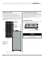
Page 29: ...12 13 14 1 18 5 22 11 28 29 30 31 32 33 34 15 2 19 6 23 12 16 3 20 9 26 7 24 13 17 4 21 10 27 8 25 14 Vertical Height In Mantle width In Concrete board Combustible facing allowed on D36 and D48 above this line Combustible facing allowed on D72 above this line Combustible mantle allowed Edge of door frame Sidewall Top of fireplace opening 1 8 Gap TOP OF UNIT METAL FRAMING KIT Finishing Around the F...

Page 30: ...ee tabs at the base of the screen Figure 20 b Lift out the Retaining Tabs and screen NOTICE STEP 1 Remove lower valve blinds and screen setting bar STEP 1 The upper frame of the door is pushed into the top channel before the bottom is pushed into place STEP 2 Ensure the tool is firmly in the lower end of the slot as shown Then pull toward you door will unlatch repeat for other buckles STEP 2 Buckl...

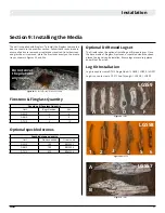
Page 31: ... any media Optional Driftwood Logset The Fireplace has the option of installing a drift wood log set Once the base media of fireglass firestones or speckled stones has been placed the log set can be installed Ensure logs are securely placed and will not tip or fall Log Kit Installation Log kits used to create D7215 Single Sided 1 LGS58 1 LGS59 1 LGS57 Log kits used to create D7215 See Through 1 LG...

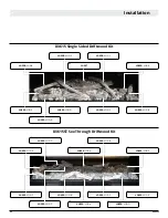
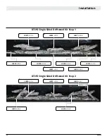
Page 32: ...S59 LOG F LGS59 LOG B LGS58 LOG 5 LGS58 LOG 1 LGS57 D3615 Single Sided Driftwood Kit D3615ST See Through Driftwood Kit LGS59 LOG E LGS59 LOG E LGS59 LOG B LGS59 LOG F LGS59 LOG A LGS59 LOG E LGS59 LOG D LGS59 LOG B LGS59 LOG D LGS59 LOG A LGS59 LOG C LGS59 LOG C LGS59 LOG F ...

Page 33: ... LOG E LGS59 LOG D LGS59 LOG B LGS59 LOG D LGS59 LOG A D4815ST See Through Driftwood Kit LGS59 LOG C LGS59 LOG C LGS59 LOG F LGS58 LOG 6 LGS59 LOG F LGS59 LOG B LGS59 LOG D LGS58 LOG 5 LGS58 LOG 4 LGS57 LGS57 D4815 Single Sided Driftwood Kit LGS59 LOG E LGS59 LOG A LGS58 LOG 1 ...

Page 34: ... LGS58 LOG 6 LGS59 LOG F LGS58 LOG 5 LGS57 LOG A LGS58 LOG 1 LGS58 LOG 4 LGS59 LOG B LGS59 LOG D LGS58 LOG 2 LGS59 LOG A LGS58 LOG 3 LGS59 LOG C LGS59 LOG E D7215 Single Sided Driftwood Kit Step 1 D7215 Single Sided Driftwood Kit Step 2 ...

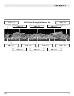
Page 35: ...XG0222 35 Installation LGS58 LOG 4 LGS59 LOG E LGS58 LOG 3 LGS59 LOG A LGS58 LOG 2 LGS58 LOG 5 LGS59 LOG F LGS59 LOG B LGS58 LOG 1 LGS59 LOG D LGS59 LOG C LGS59 LOG 6 D7215 See Through Driftwood Kit ...

Page 36: ...ITE GREEN Lights ON OFF CONTROL MAIN Power 120VAC 60 Hz 6 Amps SPARK SENSOR RED BLACK BATTERY PACK MAIN ON OFF SWITCH YELLOW GREEN PILOT R ORANGE GREEN BLACK BROWN YELLOW ORANGE 6 10 6 OPTIONAL CPI IPI SWITCH WHITE LED Lights LED1 Red LED LED2 Amber LED SW1 LED o tro e r LED power s pp y white white white BLACK WHITE VARIABLE SPEED COMFORT FANS Multicolored LED Lights Fan Kit only available in Sin...

Page 37: ...lace instructions 10 Loop Pilot wires from behind control board drawer to the front Plug into X2 and X3 8 Place Fan wire on leftside firebox floor with adhesive wire pad For fan Install instructions see Optional fan kit Install Replace instructions 11 Valve wires are plugged into the valve in the Green Red and yellow ports respectively Figure 24 e On Off switch through drawer Figure 24 i LED wire ...

Page 38: ...oor please see the door install removal section For instructions on how to remove the burner tray please see the burner tray section 4 Place Glass plate where metal plate sat before secure using existing metal brackets Screw in halfway on one side first then fully on the other side then fully tighten first side 5 Reinstall burner strip 6 Reinstall media tray 7 Reinstall pilot cover and door screen...

Page 39: ...efore you begin Always ensure the kit part number is correct for the fireplace model and all kit contents are included The model number may be found on the rating plate under the valve blind of the fireplace Installation Step 1 Slide back panel s into top track carefully push the base of the panel onto the lower ledge Step 2 Side panels are slid into the lower track and set into place using the pr...

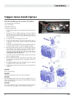
Page 40: ...rews into the valve body Use a standard screwdriver or T20 Torx bit and tighten to the screws with a fixing torque of 251b in 5 IN THE EVENT THAT THE THREADS OF THE VALVE ARE STRIPPED OR DAMAGED REPLACE THE VALVE 7 Install the enclosed identification label G to the valve body where it can be easily seen 8 Make STEPPER MOTOR and valve electrical connections apply gas to system and relight appliance...

Page 41: ... Locate fan wiring harness 5 Connect control board connector located fastened on the bottom leftside of the firebox to fan harness 6 Connect fans to harness connectors tuck wires away from LED strip To Fan To Control Box To Fan To Fan Figure 27 Fan kit Figure 27 b prepare velcro strips Figure 27 c secure the fans Figure 27 d secure the fans Figure 27 e Locate fan wiring harness Figure 27 f Connect...

Page 42: ...Red Diagnostic Light LED2 Amber Programing Remote Control Light Power 3 15A Fuse Stepper Motor Main Harness Main ON OFF Switch Sensor Igniter Manifold Pressure Test Connection Pilot Adjustment Screw Inlet Pressure Test Connection Output Regulator Control Optional ...

Page 43: ...rete board measurement includes 2 to allow coverage of the recommended fireplace platform and to avoid driving screws into important components inside the fireplace box NOTICE Cement Board Install Install the supplied non combustible cement board to overlap the new horizontal vertical 2 x 4 s place the non combustible wall board above the fireplace throat allowing 1 8 clearance from the rim above ...

Page 44: ...ments 1 Pilot Assembly 2 Proflame Gas Valve 3 Proflame 2 Control Module 4 Wiring Harness 5 Variable Speed fans 6 AUX Button turns power ON to the LED Controller 7 Proflame 2 remote control 8 Battery Pack 9 Manual override switch NOTE Can not be used with home automation systems SW1 Programing Button LED1 Red Diagnostic Light LED2 Amber Programing Remote Control Light Blue Back lit LCD display On O...

Page 45: ...e time Look at the LCD screen on the Remote Control to verify that a C or F is visible to the right of the Room Temperature display Turn On the Fireplace With the system Off turn the master override switch to on and press the On Off Key on the Remote Control The Remote Control display will show some other active Icons on the screen At the same time the Control Module will activate the fireplace A ...

Page 46: ... will change to show that the room thermostat is On and the set temperature is now displayed To adjust the set temperature press the Up or Down Arrow Keys until the desired set temperature is displayed on the LCD screen of the Transmitter Smart Thermostat Remote Control Operation The Smart Thermostat function adjusts the flame height in accordance to the difference between the set point temperatur...

Page 47: ...ally take out one battery see Figure 26k 2 Insert the battery while holding down the thermostat button The remote screen will display Clr while the button is held down See Figure 26l 3 To enable thermostat repeat steps 1 2 The remote screen will display set while the thermostat button is held down Accent Light Control The fireplace may be equipped with accent lights The auxiliary function controls...

Page 48: ... Adjustable 19 Yellow color glitters Adjustable Adjustable 20 Circulation mode Item Parameters Working Voltage AAA 2pcs 3V Radio Frequency 2400 2483 5MHz Modulate Method GFSK Transmit Power 6db Standby Power Consumption 10uA Remote Distance 20 30m Dimension 110 52 30mm Figure 30 LED remote Figure 30 b Remote parameters Figure 30 c Remote modes Use AUX function to turn power on to LED NOTE The colo...

Page 49: ...m During the initial firing Silicone seals will off gas leaving a visual deposit of a white substance on combustion chamber walls This can easily be removed using normal household products Use a vacuum cleaner or whisk broom to keep the control compartment burner and firebox free from dust and lint Section 10 Cleaning and Maintenance Annual inspection list for determining safe operation of a direc...

Page 50: ...tion air inlet to other appliance for appliance 100 000 BTU H 30 KW 12 inches 12 inches M clearance to forced air supply inlet 6 feet 3 feet above air inlet N clearance above paved sidewalk or paved driveway located on public property 7 feet 7 feet P clearance under veranda porch deck or balcony 22 inches to combustibles 16 inches to non combustibles 22 inches to combustibles 16 inches to non comb...

Page 51: ...s NG or liquefied petroleum LP only Burning conventional fireplace fuels such as wood coal or any other solid fuel will cause damage to the appliance produce excessive temperatures will result in a fire hazard and void all warranties This warranty is transferable The appliance must remain in its original place of installation to be valid If the components of the appliance covered by this warranty ...

Page 52: ...en consent of The Companies The Companies shall in no event be responsible for any warranty work done without first obtaining the Companies written consent The Companies employees and dealers have no authority to make any warranties to neither alter this warranty nor authorize any remedies in addition to or inconsistent with those stated within this warranty IF WARRANTY SERVICE IS NEEDED To make a...

Page 53: ...sign shall read in print size no less than one half 1 2 inch in size GAS VENT DIRECTLY BELOW KEEP CLEAR OF ALL OBSTRUCTIONS Appendix C Amendment Gas Fireplace Equipment sold in the State of Massachusetts 5 08 Modifications to NFPA 54 Chapter 10 4 INSPECTION The state or local gas inspector of the side wall horizontally vented gas fueled equipment shall not approve the installation unless upon insp...

Page 54: ...XG0222 Installation Maintenance Manual DISTINCTION Vented gas fireplace heater ...

Reviews: