350 SPORT YACHT
36
The generator is supplied fuel from the port tank
only and uses a withdrawal tube that is shorter
than the main engine tube to prevent the genera-
tor from exhausting the reserve fuel in the tank.
Fuel withdrawal lines on gasoline fuel systems are
equipped with anti-siphon valves where the lines
attach to the fuel tank. These valves prevent
gasoline from siphoning out of the fuel tank should
a line rupture. Diesel fuel systems are not equipped
with anti-siphon valves.
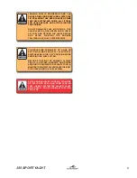
IF A FUEL LINE SHOULD LEAK, ANTI-SIPHON
VALVES PREVENT A SUBSTANTIAL AMOUNT
OF FUEL FROM FLOWING INTO THE BILGE.
SHOULD AN ANTI-SIPHON VALVE BECOME
CLOGGED, CLEAN AND REINSTALL OR
REPLACE. DO NOT REMOVE THE ANTI-SIPHON
VALVES FROM THE SYSTEM. ANTI-SIPHON
VALVES ARE REQUIRED, BY THE U.S. COAST
GUARD, TO BE INSTALLED IN ALL BOATS
EQUIPPED WITH GASOLINE ENGINES.
Fuel Gauges
This indicates the amount of fuel in the tanks.
Due to the mechanical nature of the fuel senders,
variations in readings during various speeds of
operation may occur. This system is merely a
relative indication of the available fuel supply and
not a calibrated instrument.
There is a fuel gauge sender located in the top of
each tank that are connected to fuel gauges at
the helm.
Fuel Fills
The fuel fill deck plates are located on both sides
of the transom and are marked “GAS” or “Diesel.”
The fuel fill is opened by turning it counter clock-
wise with a special key. Be sure to use the proper
type and grade fuel. Refer to the engine owner’s
manual for additional information on the fuel re-
quirements for your engines.
Note: Do not over tighten the fuel cap. If the
cap is over tightened, the O-ring seal
could be damaged allowing water to
contaminate the fuel system.
DO NOT CONFUSE FUEL FILL DECK PLATES
WITH THE WATER OR WASTE FILL DECK PLATES.
THESE PLATES ARE ALSO LABELED
ACCORDINGLY. IF GASOLINE OR DIESEL FUEL
IS ACCIDENTALLY PUMPED INTO THE WATER
OR WASTE TANK, DO NOT ATTEMPT TO PUMP
IT OUT YOURSELF. WATER AND WASTE PUMPS
ARE NOT DESIGNED TO PUMP FUEL AND A FIRE
OR EXPLOSION COULD RESULT. CONTACT
YOUR DEALER OR THE MONTEREY CUSTOMER
SERVICE DEPARTMENT FOR ASSISTANCE IN
HAVING THE FUEL PROFESSIONALLY REMOVED.
Fuel Vents
There are fuel vent fittings located on each side
of the hull. While the tanks are being filled, the
air displaced by the fuel escapes through the
vents. When the tank is almost full, fuel will be
ejected from the fuel vent. You should calculate
the amount of fuel you need to avoid overfilling
the tank and ejecting fuel from the vent or fuel
fill.
After fueling, replace the fill caps, and wash the
areas around the fuel fill plate and below the fuel
vents. Residual fuel left on the hull sides can be
dangerous, and will yellow the gelcoat or damage
the striping.
3.2 Gasoline Engine Fuel Systems
The gasoline fuel system on the 350 Sport Yacht
has two fuel tanks and two manual fuel valves.
There is one valve for each engine fuel supply.
The fuel valves are located in the engine com-
partment, just below the hatch. The fuel valves
allow the operator to run the engines from either
the port tank, which fills from the port gunnel, or
the starboard tank, which fills from the starboard
gunnel.
During normal operation, the port engine should
be supplied fuel from the port tank and the star-
board engine supplied fuel from the starboard tank
(both selector valves set to the “NORMAL” posi-
tion.) If a fuel supply problem should occur in one
of the fuel tanks, both engines can be temporarily
operated from either the port or starboard fuel
tank by setting both valves on that tank. Refer to
Fuel Tanks and Fuel Selector Valves at the begin-
ning of this chapter for more information on the
operation of the fuel tank selector valves.
The fuel valves provide a means to turn off the
fuel supply to service the fuel system. Always
make sure all fuel valves are open and set to the
proper tank when the engines are operating.
Summary of Contents for 350 Sport Yacht
Page 1: ......
Page 2: ...350 SPORT YACHT 2...
Page 6: ...350 SPORT YACHT 6 THISPAGEWASLEFTBLANK INTENTIONALLY...
Page 18: ...350 SPORT YACHT 18 THISPAGEWASLEFTBLANK INTENTIONALLY...
Page 22: ...350 SPORT YACHT 22 THISPAGEWASLEFTBLANK INTENTIONALLY...
Page 34: ...350 SPORT YACHT 34 THISPAGEWASLEFTBLANK INTENTIONALLY...
Page 42: ...350 SPORT YACHT 42 THISPAGEWASLEFTBLANK INTENTIONALLY...
Page 95: ...95 350 SPORT YACHT 11 9 Caution and Warning Labels Warning Label Locations...
Page 96: ...350 SPORT YACHT 96 THISPAGEWASLEFTBLANK INTENTIONALLY...
Page 99: ...99 350 SPORT YACHT...
Page 114: ...350 SPORT YACHT 114 THISPAGEWASLEFTBLANK INTENTIONALLY...
Page 120: ...350 SPORT YACHT 120 THISPAGEWASLEFTBLANK INTENTIONALLY...
Page 121: ...121 350 SPORT YACHT MontereyWire Legend Appendix A SCHEMATICS...
Page 122: ...350 SPORT YACHT 122 Hull Electrical 1...
Page 123: ...123 350 SPORT YACHT Hull Electrical 2...
Page 124: ...350 SPORT YACHT 124 Hull Electrical 3...
Page 125: ...125 350 SPORT YACHT LewmarWindlass RelayWiring...
Page 126: ...350 SPORT YACHT 126 Trim Tab Wiring...
Page 127: ...127 350 SPORT YACHT Gas RelayWiring...
Page 128: ...350 SPORT YACHT 128 Diesel Halon RelayWiring...
Page 129: ...129 350 SPORT YACHT Generator Remote Starting...
Page 130: ...Hull Harness 1...
Page 131: ......
Page 132: ......
Page 133: ......
Page 134: ...350 SPORT YACHT 134 Panel Hatch Relay...
Page 135: ...135 350 SPORT YACHT Battery Switch Panel...
Page 136: ...350 SPORT YACHT 136 Arch Harness...
Page 137: ...137 350 SPORT YACHT Guage Panel...
Page 138: ...350 SPORT YACHT 138 Port Switch Panel...
Page 139: ...139 350 SPORT YACHT Starboard Switch Panel...
Page 140: ...350 SPORT YACHT 140 Port Ignition Panel...
Page 141: ...141 350 SPORT YACHT Breaker Panel...
Page 142: ...350 SPORT YACHT 142 Helm Harness...
Page 143: ...143 350 SPORT YACHT Helm Instrument Harness...
Page 144: ...350 SPORT YACHT 144 Helm Harness...
Page 145: ...145 350 SPORT YACHT AC DC Deck Harness...
Page 146: ...350 SPORT YACHT 146 AC DC Deck Harness...
Page 147: ...147 350 SPORT YACHT AC DC Deck Harness 220V...
Page 148: ...350 SPORT YACHT 148 AC DC Deck Harness 220V...
Page 149: ...149 350 SPORT YACHT DC Panel...
Page 150: ...350 SPORT YACHT 150 AC DC Head Harness...
Page 151: ...151 350 SPORT YACHT AC DC Head Harness 220V...
Page 152: ...350 SPORT YACHT 152 AC Harness 120V...
Page 153: ...153 350 SPORT YACHT AC Harness 120V...
Page 154: ...350 SPORT YACHT 154 AC Harness 120V...
Page 155: ...155 350 SPORT YACHT AC Harness 220V...
Page 156: ...350 SPORT YACHT 156 AC Harness 220V...
Page 157: ...157 350 SPORT YACHT AC Harness 220V...
Page 158: ...350 SPORT YACHT 158 AC Panel 120V...
Page 159: ...159 350 SPORT YACHT AC Panel 220V...
Page 160: ...350 SPORT YACHT 160 Shore Power Inlet Panel 120V...
Page 161: ...161 350 SPORT YACHT Shore Power Inlet Panel 220V...
Page 162: ...350 SPORT YACHT 162 Digital Generator Adapter Harness...
Page 163: ...163 350 SPORT YACHT 8402Wire Guide...
Page 164: ...350 SPORT YACHT 164 KAC6402 SET UP KAC8402 SET UP...
Page 165: ...165 350 SPORT YACHT Generator System...
Page 166: ...350 SPORT YACHT 166 Gasoline and Diesel Engine Fuel System Fuel Valves...
Page 167: ...167 350 SPORT YACHT Air Conditioning...
Page 168: ...350 SPORT YACHT 168 Water System...
Page 169: ...169 350 SPORT YACHT Bilge and Drain 1...
Page 170: ...350 SPORT YACHT 170 Bilge and Drain 2...
Page 171: ...171 350 SPORT YACHT Waste System...
Page 172: ...350 SPORT YACHT 172 Proper Cradle Support...
Page 174: ...350 SPORT YACHT 174 MAINTENANCE LOG Hours Date Dealer Service Repairs...
Page 175: ...175 350 SPORT YACHT MAINTENANCE LOG Hours Date Dealer Service Repairs...
Page 176: ...350 SPORT YACHT 176 MAINTENANCE LOG Hours Date Dealer Service Repairs...
Page 177: ...177 350 SPORT YACHT MAINTENANCE LOG Hours Date Dealer Service Repairs...
Page 178: ...350 SPORT YACHT 178 MAINTENANCE LOG Hours Date Dealer Service Repairs...
Page 180: ...350 SPORT YACHT 180 THISPAGEWASLEFTBLANK INTENTIONALLY...
Page 193: ...193 350 SPORT YACHT...
Page 195: ...Hull Harness 1...
Page 196: ......


