


30
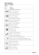
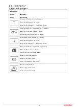
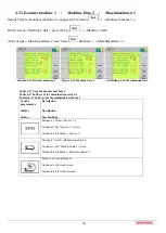
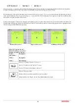
Table 4-12 Machine data 1
Parameters
Description
Row quantity
The total number of units is to be set here. This figure is required for the
operating width of the machine and for determining the tramline rhythm.
Row spacing
Distance between two adjacent units. This figure is required for
determining the tramline rhythm.
No. of holes
Number of holes in the sowing disc
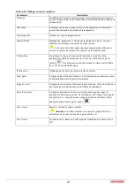
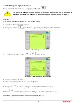
Pulses/100m
Here the pulses / 100m are set for the speed sensor. If the value is
unknown, a calibration can be performed.
!
This value must be set very precisely, since it influences the speed,
the area measurement and the monitoring of the output quantity.
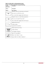
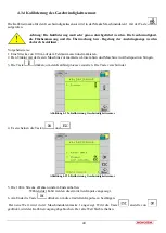
Blower target
Here the blower speed, which should be monitored, is inputted. It is also
possible to save the current blower speed by using the
key. If the
rotational speed deviates from the setpoint by more than ±10%, an alarm
is emitted.
Blower current
Indication of the current blower speed
Spray width
Working width of the plant protection spray, which is used for
maintaining crops. This figure is required for determining the tramline
rhythm.
Tr. track width
Track width of tractor, with which plant protection measures are carried
out. This figure is required for determining the tramline rhythm.
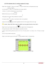
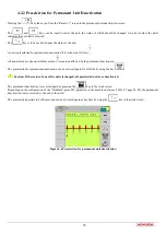
Headland –perm.PW
With this setting it is possible to determine whether the permanent
deactivation of units at the end of the field is reversed again or not. With
the setting "off", the permanent deactivation is retained. If all units
should be used again, the deactivation must be reversed by using the
key.
Sim. speed
Here the simulated speed can be activated and deactivated.
!
Caution:
The simulated speed is retained until the job computer is
switched off or it is switched off again.
Sim. speed
This speed is simulated if the simulated speed is activated.
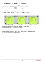
Summary of Contents for CS 6200-24
Page 3: ...1 Notice d utilisation ...
Page 17: ...15 ...
Page 37: ...35 ...
Page 43: ...41 ...
Page 54: ...52 ...
Page 55: ...53 PIECES DE RECHANGE SPARE PARTS ERSATZTEILE ...