background image

23 

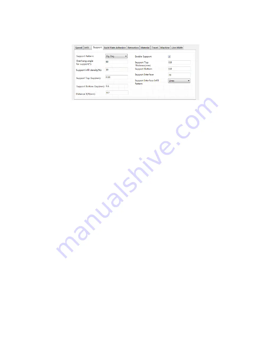
Support Tab 


Support Pattern: Use the drop-down menu to select one of five support patterns, 
including Lines, Grid, Triangles, Zig Zag, and Concentric. The pattern designs are the 
same as those of the infill patterns of the same name. 

o


Lines support is easier to remove and is used on models that require more 
support. 

o


Grid support is used on small models, which need fewer supports. 

o


Zig Zag support is used for models that are particularly difficult to remove. It is 
stronger than Lines support and is better than Grid support. 


Overhang angle: The overhang angle is the angle between the support and the 
surface of the model. Larger settings make the supports easier to remove, while 
smaller settings provide better support. The default angle is 60 degrees. 


Support infill density (%): Determines the infill density for supports. The higher the 
density, the stronger the supports. 


Support Top Gap (mm): The distance between the top of the support and the 
model surface. The smaller the distance, the more effective the support, but is more 
difficult to remove from the model surface, resulting in residual material on the 
model surface. The larger the distance, the less effective the support, but is easier 
to remove from the model surface, resulting in a smoother surface. 


Support Bottom Gap (mm): The distance between the bottom of the support and 
the model surface. The effects of this parameter are the same as the effects of the 
Support Top Gap (mm) parameter. 

Summary of Contents for Maker Ultimate 2

Page 1: ...Maker Ultimate 2 3D Printer P N 36045 User s Guide ...

Page 2: ...W 8 Right Side View 9 MENU SYSTEM 10 Menu Map 10 Menu Operation 10 Main Menu 11 Info Screen 12 Prepare Menu 12 Move Axis Menu 13 Control Menu 14 Temperature Menu 15 Door Open Check Menu 15 WIIBUILDER SLICING SOFTWARE 16 Installation 16 WiiBuilder Setup 18 Speed Tab 20 Infill Tab 21 Support Tab 23 Build Plate Adhesion Tab 24 ...

Page 3: ...ab 30 Others Tab 31 GETTING STARTED 33 CARE AND MAINTENANCE 35 Cleaning the Nozzle 35 Clearing a Blocked Nozzle 35 Replacing the Tape on the Build Platform 37 Optical Shaft and Screw Rod Maintenance 37 Cleaning the Feed Gear 37 SPECIFICATIONS 39 TECHNICAL SUPPORT 40 REGULATORY COMPLIANCE 40 Notice for FCC 40 Notice for Industry Canada 41 ...

Page 4: ...ged from its power source before making repairs or performing service Do not install this device on an unstable surface where it could fall and cause either personal injury or damage to the device and or other equipment Do not subject the product to extreme force shock or fluctuations in temperature or humidity This device is intended for indoor use only Do not expose this device to water or moist...

Page 5: ...ver direct the scraper towards your fingers or body The printer is designed to operate with an ambient temperature ranging from 41 F 5 C to 104 F 40 C Printing outside these limits may result in low quality prints Use eye protection when cleaning or sanding the printed models to avoid getting small particles in your eyes INTRODUCTION Thank you for purchasing this Maker Ultimate 2 3D Printer This p...

Page 6: ... sec Includes WiiBuilder slicing software Includes 8GB microSD card Fully assembled CUSTOMER SERVICE The Monoprice Customer Service department is dedicated to ensuring that your ordering purchasing and delivery experience is second to none If you have any problem with your order please give us an opportunity to make it right You can contact a Monoprice Customer Service representative through the L...

Page 7: ...rvice for a replacement 1x 3D printer 1x 500g spool of PLA filament 1x Filament holder 1x 8GB microSD card 1x microSD card reader 1x Metal scraper 1x USB cable 1x Switch cable 1x Motor cable 1x Set of Allen keys 1x Roll yellow tape 1x Spanner 1x Stick of water washable glue 1x US power cord 1x UK power cord 1x EU power cord 5x User s manuals English Deutsche Español Français Italiano ...

Page 8: ...8 PRODUCT OVERVIEW Front View 1 Top Cover 2 Front Door 3 AC Power Socket and Power Switch 4 LCD Display 5 Control Knob 6 Heated Build Platform 7 Nozzle ...

Page 9: ...9 Right Side View 1 Filament Holder 2 microSD Card Slot 3 USB Port ...

Page 10: ...unterclockwise to move the menu highlight up or to the left If on a menu or submenu turn the Control Knob clockwise to move the menu highlight down or to the right If on a menu or submenu push the Control Knob to enter the highlighted submenu or to select the highlighted entry for editing If editing a value turn the Control Knob counterclockwise to decrease the value ...

Page 11: ...replaced with the Tune option Tune Opens the Tune submenu When not printing a model the Tune option is replaced with the Prepare option Control Opens the Control submenu Print from SD Displays a list of gcode files on the inserted microSD card If a microSD card is not inserted the line will read No SD card Pause Resume print When printing a model select Pause print to pause the print While the pri...

Page 12: ...Main option to return to the Main Menu Filament In Loads filament Retract Unloads filament Auto home Moves the extruder and build platform to their home positions Set home offsets Displays the Set Home Offsets screen Move axis Opens the Move Axis menu Cancel all Cancels all printer operations ...

Page 13: ...e 0 1mm option displays the movement screen as shown on the right above allowing you to move the X Y and Z axes as well as the extruder Move axis Select the Move axis option to return to the Control Menu Move X Select the Move X option to open the Move X Edit Screen Rotate the Control Knob to move the extruder along the X axis then press it to save the value and return to the Move Axis Menu Move Y...

Page 14: ... 1mm Extruder Select the Extruder option to open the Move Extruder Edit Screen Rotate the Control Knob to push filament in or out then press it to save the value and return to the Move Axis Menu This option will only be visible when choosing 1mm or 0 1mm Control Menu Main Select the Main option to return to the Main Menu Level bed Starts the bed leveling process Temperature Opens the Temperature M...

Page 15: ...set the temperature then press it to save the value and return to the Temperature Menu Bed Select the Bed option to open the Bed Temperature Edit Screen Rotate the Control Knob to set the temperature then press it to save the value and return to the Temperature Menu Door Open Check Menu When enabled opening the door will pause printing When disabled opening the door will have no effect ...

Page 16: ... and run the WiiBuilder exe software on the microSD card to install the WiiBuilder software program The Installer will prompt you for the language to use in the InstallShield Wizard Use the pull down menu to select your preferred language then click the OK button to continue 2 The Wizard will prompt you to select the install location If you don t want to use the default install location use the Br...

Page 17: ...17 3 Click the Install button to continue 4 Once the installation is complete click the Next button to continue 5 Click the Finish button to complete the installation and launch the program ...

Page 18: ...e slice buttons etc Read each page clicking the next button to proceed from page to page Click the finished button on the final page to close the Wizard 2 Once the Wizard closes you will be prompted to select the printer model and the units of measure you want to use MP Maker Ultimate2 is the default selection Click the OK button to continue 3 Click the Config GUI Choices Expert GUI ...

Page 19: ...19 4 Click one of the Slice buttons to display the Basic Configure dialog 5 Click the Advanced Configure button to display the following dialog The following sections detail the options on each tab ...

Page 20: ...nting speed of the internal shell surfaces Infill Speed mm s Sets the printing speed of the infill inside the model Support Infill Speed mm s Sets the printing speed of infill inside the model supports Support Interface Speed mm s Sets the printing speed of the top and bottom surfaces of the model supports Initial Layer Speed mm s Sets the printing speed of the first layer of the model Travel spee...

Page 21: ...s are illustrated in the table below Infill Before Wall Check this box to print the model after filling and printing the outline Outer Before Inner Walls Check this box to print the exterior walls before printing the interior walls Gradual Infill Steps For models that need to gradually change the fill rate this value determines how many layers to change at once Infill Patterns Lines Grid ...

Page 22: ...22 Triangle Zig Zag Concentric Cross Octet ...

Page 23: ...odel Larger settings make the supports easier to remove while smaller settings provide better support The default angle is 60 degrees Support infill density Determines the infill density for supports The higher the density the stronger the supports Support Top Gap mm The distance between the top of the support and the model surface The smaller the distance the more effective the support but is mor...

Page 24: ...e Sets the percentage of infill used inside the supports Support Interface Infill Pattern Use this drop down menu to choose one of five infill patterns for the supports including Lines Grid Triangles Zig Zag and Concentric The pattern designs are the same as those of the infill patterns of the same name Build Plate Adhesion Tab Raft Air Gap mm The distance between the raft and the model This deter...

Page 25: ...irst and second layers of the model Brim line amount Sets the number of ring gaskets that are added to the edge of the model in contact with the build platform Skirt Line Count Sets the number of anti overflow lines at the end of the model in contact with the build platform ...

Page 26: ...retracted Retraction distance mm The distance the filament is retracted within the nozzle Z Hop Height mm The distance the nozzle is lifted when filament is returned after retraction Retraction Minimum Travel mm Sets the minimum nozzle movement distance before printing and before retracting the filament Material Tab Filament flow Sets the flow rate of filament in the melting state This is set acco...

Page 27: ...le move the shortest distance between the previous extrusion location and the new start location The All option causes the nozzle to move along anything it has already extruded The No Skin option will avoid the outer layers to move the nozzle to the new start location which can greatly improve print quality Start Layers at Same Position This option changes the accuracy of the model in the same pla...

Page 28: ... the right extruder Line Width Tab Outer Wall Line Width mm This is the width of the outermost wall line By lowering this value higher levels of detail can be printed Inner Wall s Line Width mm This is the width of a single wall line for all walls except the outermost wall Top Bottom Line Width mm This is the width of the top and bottom lines Infill Line Width mm This is the width of a single infi...

Page 29: ... Sets the temperature of the second extruder when not actively printing Prime Tower Size mm This is the extrusion width of the prime tower The prime tower is a location that the printer will use to switch nozzles during dual extrusion to prevent a gap in the model by printing a small amount of filament at the prime tower location Ooze Shield Distance mm This is the size of the circle of protection...

Page 30: ...elps reduce warping on large models Seam Tab Note The Z Seam is where the printer finishes its motion when printing the skin outside layer of a model This can result in a small blob or zit where the printer changes the Z height If in alignment there can be a noticeable line up the side of the print referred to as a Z Seam because the filament continues to ooze at the start stop location The option...

Page 31: ...n the Z Seam Type is set to User Defined Hiding Seam Preference This option is only available when the Z Seam Type is set to Sharpest Corner It determines whether the Z Seam will be on the inside or outside of the corner Z Seam Relative Checking this box will set the Z Seam in respect to the object s center whereas leaving the box unchecked will set the Z Seam along the absolute position on the bu...

Page 32: ... layers The following image illustrates the print direction of layer three when the Skin Alternate Rotation option is enabled Enable Print Cooling When enabled cooling air will be directed at the printed part Enable Draft Shield When enabled this printer will print a wall around the model to prevent environmental breezes or drafts from affecting the cooling This is typically used when Enable Print...

Page 33: ...d silicon rubber sheets on the Z axis 3 Use the included 2mm Allen wrench and the included spanner to remove the fixed support on the Z axis 4 Remove the microSD card from the accessory box and insert it in the card slot to the left of the display Next remove the included AC power cord plug one end into the AC power socket on the left side of the printer then plug the other end into a nearby AC po...

Page 34: ...nt into the sensor until it comes out of the tube 6 Press the extruder handle then insert filament into the hold to a depth of about 4cm 7 Open the Control menu then choose the Filament In options Wait for the filament to finish loading 8 Go back to the Main menu then select the Print from SD option Locate and select one of the gcode files on the microSD card to start your first print ...

Page 35: ...ilament particles can accumulate around the nozzle Use tweezers and a cleaning cloth to remove extraneous filament Clearing a Blocked Nozzle The nozzle can become blocked from time to time Perform the following steps to clear a blocked nozzle 1 Use a 2 5mm Allen wrench to loosen the screw shown in the image below and to the left then unplug the nozzle 2 Heat the nozzle to 200 C ...

Page 36: ...36 3 Grasp the heated nozzle with a pair of pliers then use a 1 5mm Allen wrench to clear the blockage 4 Reinstall the nozzle then secure it in place with the screw ...

Page 37: ...care to ensure that there are no bubbles under the tape or gaps between the strips of tape Optical Shaft and Screw Rod Maintenance After about 1000 hours of use the optical shaft and screw rod should be lubricated using silicon grease not included After lubrication run the machine through its full movement range several times to spread the lubrication evenly Cleaning the Feed Gear As the printer i...

Page 38: ...e two hex head screws on the right side then remove the motor and cooling fan 5 Use tweezers to clean the filament debris on the motor gear 6 Reinstall the motor and cooling fan then secure them in place with the two hex head screws removed in step 4 above 7 Plug the nozzle back in then tighten the screw loosened in step 3 above 8 Plug the motor connection cable back into the motor ...

Page 39: ... 0025mm Supported Filament Types ABS PLA PLA Pro TPU TPE PET Metal fill Wood fill etc Supported Software WiiBuilder Cura Simplify3D Slic3r Kisslicer Supported File Formats STL gcode OBJ Print Interface USB microSD card Supported Operating Systems Microsoft Windows Mac OS X Input Power 24 VDC 10A AC Adapter Input Power 100 240 VAC 50 60 Hz Dimensions 15 0 x 13 4 x 16 5 380 x 340 x 420 mm Weight 33 ...

Page 40: ...ed operation Modifying the equipment without Monoprice s authorization may result in the equipment no longer complying with FCC requirements for Class B digital devices In that event your right to use the equipment may be limited by FCC regulations and you may be required to correct any interference to radio or television communications at your own expense This equipment has been tested and found ...

Page 41: ...a This Class B digital apparatus complies with Canadian ICES 003 Cet appareil numérique de la classe B est conforme à la norme NMB 003 du Canada EU Declaraton of Conformity Monoprice Inc declares the product described within this user guide or manaul is in compliance with below applicable directives The full text of the EU Declaration of Conformity is available at the following internet address xx...

Page 42: ...is symbol and or its packaging must not be disposed of with unsorted municipal waste The symbol indicates that this product should be disposed of separately from regular household waste streams It is your responsibility to dispose of this and other electrical and electronics products via designated collection facilities appointed by the government or local authorities Correct disposal and recyclin...

Page 43: ...ge caused by lightning WARNING The external power adapter or AC power cord is the equipment s disconnection device The power outlet must be located nearby the equipment and its access must be easy WARNING Use this product in a well ventilated area microSD is a trademark of SD 3C LLC Microsoft and Windows are either registered trademarks or trademarks of Microsoft Corporation in the United States a...

Reviews: