PRODUCT APPLICATION SPECIFICATION
THIS DOCUMENT CONTAINS INFORMATION THAT IS PROPRIETARY TO MOLEX ELECTRONIC TECHNOLOGIES, LLC AND SHOULD NOT BE USED WITHOUT WRITTEN PERMISSION
REVISION
DESCRIPTION
REVISED
APPLICATION SPECIFICATION FOR
MICRO-LOCK PLUS 2.0 SINGLE ROW
CHANGE NO.
682239
REVISED BY
SOKUMURA01
DATE
2021/02/09
DOC TYPE
DOC TYPE DESCRIPTION
DOC PART
SERIES
REV APPR BY AIDA
DATE
2022/06/30
PS
APPLICATION SPECIFICATION WORD
A03
505570
INITIAL RELEASE
CUSTOMER
DOCUMENT NUMBER
REVISION
SHEET
INITIAL DRWN KUSATO
DATE
2016/04/20
GENERAL MARKET
5055700001
E
9
OF
49
INITIAL APPR
TKANEKO
DATE
2016/04/21
PROCEDURE: 2090580010-ES TEMPLATE: 2090580010-PAS-A4 REVISION: A1
【
4. The confirmation items of crimping wire
】
4-1. The appearance before crimping
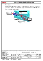
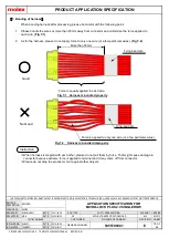
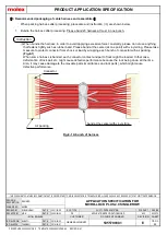
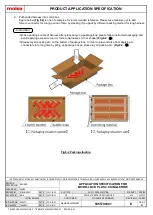
When using the loose terminals products before crimping, please make sure that there is no deformation of the
crimp terminal. If you find that the terminals are tangled, please do not remove them forcibly.
Please refer to sales drawing for product form and its dimensions.
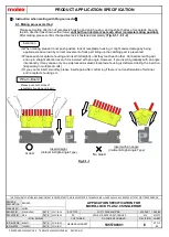
4-2. The appearance after crimping
Confirmation items and crimping failure after crimping are shown as follows.
(Fig.4-1)
Please refer to ATS for specified crimp height, pull testing, and applicable wire specification.
①
No visible damage on terminal.
②
No visible damage or deformation on contact area.
③
All wire strands are in conductor barrel.
④
The insulator part of the electric wire is located in the intermediate position of
wire barrel and insulation barrel.
⑤
No damage on lance.
⑥
No damage on appearance. (Dirt / foreign objects)
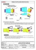
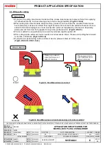
4-3. Crimping failure
Please be careful of the crimping failure as shown below.
It may affect the insertion to housing and affect a product function.
1. Bend up
It may deteriorate insertion to housing and terminal retention force or cause contact failure.
(Fig.4-2)
2. Bend down
It may deteriorate insertion to housing and terminal retention force or cause contact failure.
(Fig.4-3)
×
No Good
×
No Good
②
③
④
⑤
①
⑤
③
④
①②
Fig.4-1
Fig.4-2
Fig.4-3


