


36
Chapter 6. Optical switch
6.4
mogfzw switch UI
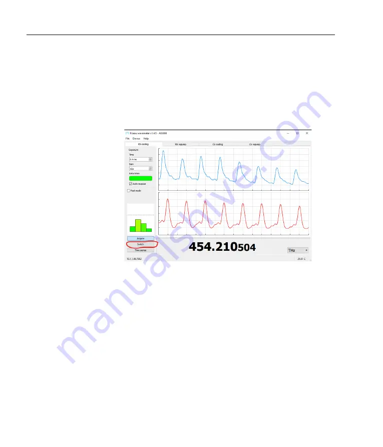
When connecting to an
FZW
that has an
FSW
optical switch attached,
the interface will show a tabbed view for the different switch inputs.
Names can be assigned to the inputs by double-clicking each tab.
When an
FSW
is connected, the
PID
button in
mogfzw
will be re-
placed with a
Switch
button (Figure 6.4).
The
FSW
switch control
Figure 6.4:
With
FSW
connected, the
PID
buttom in
mogfzw
is replaced
with a
Switch
button that opens a new dialogue for monitoring and con-
trolling the switch channels.
window shows the wavelength measurement, exposure, and optical
band setting for all channels simultaneously. Each port can be con-
figured, for example to select the optical band, or to control the
PID
parameters.
The figure below (Figure 6.5) shows the
Switch
tool
for a 4-port switch.
Port name
Double-click within the settings area for any port, to allow entry of
a name for that channel.
Enable
When auto-stepping through the ports (see below), only those with
Enable
checked will be measured; others will be skipped.
Disable
Summary of Contents for FSW4
Page 1: ...Fizeau Wavemeter and Fibre Switcher FZW600 FSM2 FSW4 FSW8 Firmware v0 9 5 mogfzw v1 4 5 ...
Page 36: ...30 Chapter 5 PID locking ...
Page 50: ...44 Appendix A Specifications ...
Page 60: ...54 Appendix C Command language ...
Page 62: ...56 Appendix D Errors and troubleshooting ...
Page 67: ...F Dimensions and PCB 83 120 146 32 9 30V PID TRIG FSW Figure F 1 FZW chassis dimensions 61 ...
Page 68: ...62 Appendix F Dimensions and PCB 146 33 37 120 18 Figure F 2 FSW fibre switch dimensions ...
Page 71: ......