Installation, Operation
and Maintenance Manual
PREPARE THE VALVE FOR
INSTALLATION
INSTALL THE VALVE
PROPERLY
MAINTAIN THE VALVE FOR
OPTIMAL OPERATION
AND PERFORMANCE
for the
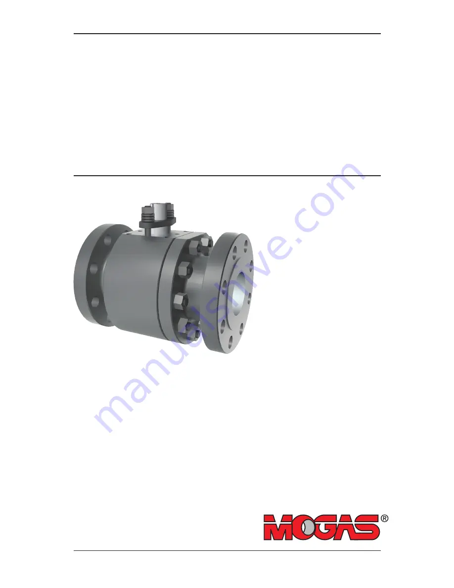
MOGAS ISOLATOR 2.0 Floating Ball Valve
1, 1.5, 2, 3 and 4 inch
Page 1: ...eration and Maintenance Manual PREPARE THE VALVE FOR INSTALLATION INSTALL THE VALVE PROPERLY MAINTAIN THE VALVE FOR OPTIMAL OPERATION AND PERFORMANCE for the MOGAS ISOLATOR 2 0 Floating Ball Valve 1 1 5 2 3 and 4 inch ...
Page 2: ...ESI 6149 Copyright 01 22 2018 MOGAS Industries Inc www mogas com 2 THIS PAGE INTENTIONALLY LEFT BLANK ...
Page 3: ...3 4 INCH 6 READ BEFORE INSTALLING VALVE 8 TRANSPORT AND STORAGE 9 CORRECT VALVE ORIENTATION 10 PRE INSTALLATION 11 INSTALLATION 12 OPERATION 14 MAINTENANCE 15 REPLACE STEM PACKING 16 DISASSEMBLY 20 EVALUATION AND REWORK 25 ASSEMBLY 26 LOCATE VALVE INFORMATION 34 RETURN MERCHANDISE AUTHORIZATIONS RMA 35 SERVICE CONTACT 36 ...
Page 4: ...ESI 6149 Copyright 01 22 2018 MOGAS Industries Inc www mogas com 4 05 07B 08 09A 09B 07C 28 63 12 15 07D 07 02 01C 01B 01A 61C 01B 10 04 03 11 Valve Item Reference Number Size 1 inch 1 inch 2 inch ...
Page 5: ...on Titanium F53 All Other Material Recommended Spare Parts 01A Ball 01B Seat Ring 01C Spring Disc 02 Body 03 End Connection 04 Gasket Spiral Wound 05 Stem 07 Gland Flange 07B Thruster Gland Flange 07C Spring Discs Live Loading 07D Washer Flat 08 Bearing Stem Seal 09A Ring Stem Packing 09B Ring Anti Extrusion 10 Stud Body 11 Nut Body 12 Stud Gland 15 Nut Gland 28 Retainer Ring External Self locking...
Page 6: ... Copyright 01 22 2018 MOGAS Industries Inc www mogas com 6 05 07B 08 09A 09B 07C 12 15 07 02 01C 01B 01A 61A 61B 62 01B 10 04 03 11 Valve Item Reference Number Size 3 inch 4 inch All other material Titanium F53 ...
Page 7: ...Titanium F53 All Other Material Recommended Spare Parts 01A Ball 01B Seat Ring 01C Spring Disc 02 Body 03 End Connection 04 Gasket Spiral Wound 05 Stem 07 Gland Flange 07B Thruster Gland Flange 07C Spring Discs Live Loading 07D Washer Flat 08 Bearing Stem Seal 09A Ring Stem Packing 09B Ring Anti Extrusion 10 Stud Body 11 Nut Body 12 Stud Gland 15 Nut Gland 28 Retainer Ring External Self locking 61...
Page 8: ...g the valve CLOSE OPEN Sequential procedure required to perform operation Bold numbers correspond with items shown in the Valve Item Reference Number sections Warning statement to prevent unwanted consequence Note s to support procedure All information within this manual is relevant to the safe and proper care of your MOGAS ball valve Please understand the following examples of instructional infor...
Page 9: ...ld remain in place REMOVING VALVE FROM SERVICE Before the valve is removed from the line it should be placed in the open position to prevent further internal damage to valve components Once removed the valve should be placed in a vertical position or raised at an angle The bore of the valve should be either steamed cleaned or power washed to remove slurry and debris The valve should be allowed to ...
Page 10: ... TOP For correct installation you must verify Flow Direction The preferred direction of flow is from the higher pressure end upstream to lower pressure end when the valve is closed In certain conditions proper operation may require the sealing seat be positioned opposed to the flow direction Pressure End Always marked on the valve prior to leaving the factory Preferred Sealing Seat Located opposit...
Page 11: ... operator manual if supplied shipped with the valve REMOVE PROTECTIVE COVERS Remove protective covers from the valve ends Inspect internally for shipping debris or damage VERIFY OPERATOR If the valve was ordered with a gear or actuator from MOGAS it should arrive pre assembled and tested from the factory If already assembled continue with the valve installation If the valve does not have a gear or...
Page 12: ...clockwise to open clockwise to close VERIFY OPERATING POSITION Verify that the ball open closed position matches the handlever or actuator open closed position indicators Note ISOLATOR 2 0 valves 3 inch or larger have scribed lines on stem ISOLATOR 2 0 valves 2 inch or smaller do not have scribed lines on stem If present verify that the scribed lines on the stem 05 align with the scribed lines on ...
Page 13: ...G DIRECTION Identify the preferred sealing direction of the valve indicated by Pressure End indicated on the valve body 02 Note The normal direction of flow is from the higher pressure end upstream to lower pressure end when the valve is closed In certain conditions proper operation may require the indicated flow be opposed to the line flow Make sure that the Pressure End is positioned toward the ...
Page 14: ...ure that the valve is fully opened and fully closed This wipes debris from the ball and ensures optimal performance and long valve life OPEN CLOSE CAUTION Throttling with ball valves is NOT recommended Prolonged exposure of a portion of the ball to flow can compromise the sealing integrity of the valve THIS WILL AFFECT THE VALVE WARRANTY Fully CLOSED position Fully OPEN position Partially OPEN pos...
Page 15: ...the bolting at these same locations periodically CAUTION If bolting torque is lower than specified values on the test certificate provided for each individual valve serial number re torque bolting as necessary THIS WILL AFFECT THE VALVE WARRANTY OPEN CLOSE VALVE REGULARLY Valves remaining open or closed for a long period of time should be cycled open closed at least once a year Valves should alway...
Page 16: ...TOP PLATE Use a flathead screwdriver to pry the retaining ring 28 up and off the stem Then slide the stop plate 63 up and off the stem Note ISOLATOR 2 0 models 3 inch and larger will not have a retaining ring or stop plate REMOVE GLAND NUTS Remove the packing gland nuts 15 and spring discs live loading 07C Remove flat washers 07D if present Note ISOLATOR 2 0 models 3 inch and larger will not have ...
Page 17: ...ing rings Note Always wear a face shield or goggles to protect eyes from flying debris PREPARE PACKING RING SET The new packing ring set will contain four rings total two anti extrusion rings 09B and two packing rings 09A Note The rings must be installed in the order shown Refer to Bill of Materials supplied with each individual valve serial number for specific quantity CAUTION If you have rings t...
Page 18: ...LL FINAL ANTI EXTRUSION RING If there is enough depth for the final anti extrusion ring to fit flush in the pocket install the anti extrusion ring 09B If there is not enough depth for the final anti extrusion ring to fit flush in the pocket the packing rings must be compressed To compress packing rings temporarily install the gland flange thruster 07B over stem 05 then the gland flange 07 and glan...
Page 19: ...TION The gland flange must be pulled down evenly to prevent cocking or side loading as this could cause damage to the packing and prevent the valve from operating properly Watch the gland flange to ensure that it remains perpendicular to the stem and the gap around the stem remains concentric during the tightening process Do not over tighten nuts Torque all nuts evenly per the specifications inclu...
Page 20: ...alve disassembly REMOVE OPERATOR If operator is present remove per instructions provided by manufacturer REMOVE MOUNTING FLANGE ADAPTOR If mounting flange adaptor is present it must be removed Note Mark any matching components with a marker tape etc prior to disassembly for ease of reassembly 1 2 Before beginning any work identify the valve model by checking the number on the side of the valve bod...
Page 21: ...isassembly for ease of reassembly Optional based on model Optional based on model CAUTION Do not damage seat pocket when removing seat ring REMOVE SEAT RING Note ISOLATOR 2 0 models and sizes have different seat retention designs Sizes 2 inch or smaller use a seat retaining ring 61C located in body cavity The seat ring 01B can be removed freely from end connection 03 Sizes 3 inch or larger use a s...
Page 22: ...A is clear of body 02 10 11 REMOVE SPRING DISC Remove spring disc 01C from body 02 13 REMOVE SEAT RING Remove seat ring 01B from body 02 12 Disassembly CAUTION Do not damage sealing surface inside body gasket counter bore REMOVE BODY GASKET Remove body gasket 04 from body 02 08 REMOVE SEAT RETAINING RING If present remove seat retaining ring 61C from body 02 Note Some ISOLATOR 2 0 models have diff...
Page 23: ...D if present Note ISOLATOR 2 0 models 3 inch and larger will not have flat washers REMOVE GLAND FLANGE Lift upward to remove the packing gland flange 07 REMOVE GLAND STUDS Remove gland studs 12 from body 02 REMOVE GLAND FLANGE THRUSTER Lift upward to remove the packing gland flange thruster 07B REMOVE STEM Using a hammer and brass or aluminum rod or wooden block tap stem 05 into body cavity Carefu...
Page 24: ...ch the stem or the packing bore in the body Scratches could cause a leak 21 REMOVE STEM SEAL Remove inner stem seal 08 from stem 05 20 CLEAN PACKING BOX Before installing the new packing make sure the packing box is clean If needed use an air hose to clean debris from packing box before installing new packing rings Note Always wear a face shield or mono goggles to protect eyes from flying debris 2...
Page 25: ... Valve Item Reference Number page 5 and 7 for a recommended spare parts list Contact MOGAS or a MOGAS Authorized Repair Center to determine the spare parts and quantities required for your specific circumstance EVALUATION Contact MOGAS for inspection and evaluation to determine if rework of components may be necessary Note For rework procedures see C Series IOM which is available from our Media Ce...
Page 26: ...Y All seals gaskets springs and packing must be replaced with new materials during assembly to ensure proper valve operation Note Refer to Valve Item Reference Number drawings pages 4 7 for identification of all seals gaskets spring s and packing 02 INSTALL STEM SEAL Place inner stem seal 08 on stem 05 CAUTION Inner stem seals are coated on both sides so no special orientation is required 02 INSER...
Page 27: ... anti extrusion rings 09B and two packing rings 09A Note The rings must be installed in the order shown Refer to Bill of Materials supplied with each individual valve serial number for specific quantity CAUTION If you have rings that contain skive cuts see illustration the location of each skive cut must be staggered or alternated during installation This is done to prevent formation of a possible...
Page 28: ...ket INSTALL FINAL ANTI EXTRUSION RING If there is enough depth for the final anti extrusion ring to fit flush in the pocket install the anti extrusion ring 09B If there is not enough depth for the final anti extrusion ring to fit flush in the pocket the packing rings must be compressed To compress packing rings temporarily install the gland flange thruster 07B over stem 05 then the gland flange 07...
Page 29: ...land nuts 15 and torque all nuts evenly per the specifications included with the test certificate for each individual valve serial number CAUTION The gland flange must be pulled down evenly to prevent cocking or side loading as this could cause damage to the packing and prevent the valve from operating properly Watch the gland flange to ensure that it remains perpendicular to the stem and the gap ...
Page 30: ... an odd number fit the body only seats identified with an even number fit the end connection only Seat ring identification is also provided inside the stem slot of the ball to ensure correct assembly 12 Note Matching Identification The seat rings are uniquely mate lapped to the ball Seats identified with an odd number fit the body only seats identified with an even number fit the end connection on...
Page 31: ...pocket Note The seat rings are uniquely identified to fit only a body or end connection Seats identified with an odd number fit the body only seats identified with an even number fit the end connection only Seat ring identification is also provided inside the stem slot of the ball to ensure correct assembly 17 Sizes 2 inch or smaller use a seat retaining ring 61C already installed in body cavity A...
Page 32: ... end flanges as well as match marks made during disassembly Note MOGAS valve flanges are supplied in the customary straddle centerline hole orientation unless otherwise specified Lower end connection onto body face Watch that seat ring does not fall out or crush body gasket 18 SECURE END CONNECTION Apply anti seize compound on body studs 10 and nuts 11 Install nuts 11 alternately tightening all nu...
Page 33: ...hould be stroked one full cycle to ensure that the ball is rotating properly If valve does not stroke smoothly disassemble and take corrective action Note Larger valves may require the actuator to be in place to rotate the ball 20 TORQUE BODY BOLTING Torque the valve body bolting to secure the body 02 and end connection 03 assembly CAUTION Torque the valve body bolting per the specifications inclu...
Page 34: ... number that can be used to decipher the valve configuration including size pressure class inlet outlet connection body material ball and seat trim coating stem material maximum temperature and operator as seen below Additional information may also be provided on identification tags per customer request IS100 01 F F SS 1 1 1 65 1 example 1 inch ASME 150 Class RFF inlet RFF outlet A182 F316 body 31...
Page 35: ...ia what goes through the valve Total estimated cycles from last installation Operating temperature max F Operating pressure max PSI Actuator specifics Contact the MOGAS Service department to obtain authorization and to receive shipping instructions The RMA request may also be submitted online by accessing the Service page of our website www mogas com MOGAS Service may be reached 24 hours per day 7...
Page 36: ...ure differentials Velocity control Noise control MOGAS INDUSTRIES INC Headquarters 14330 East Hardy Street Houston TX USA 77039 1405 Phone 1 281 449 0291 Fax 1 281 590 3412 E mail mogas mogas com AUSTRALIA Phone 61 0 8 9456 3533 CANADA Phone 1 780 436 4485 CHINA Phone 86 0 10 8454 9478 EUROPE Phone 44 0 1162 793367 MIDDLE EAST Phone 971 0 4 889 5667 To locate a sales and service center in your are...