


22
Visit our website at http://modeltech.globalhobby.com or for Customer Service at http://globalservices.globalhobby.com
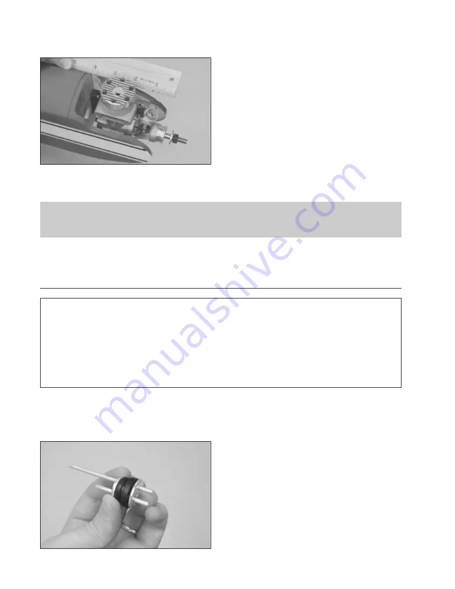
Step 3: Aligning and Installing the Engine
❑
Set the engine onto the engine mounting beams.
❑
Using a ruler, measure the distance from the firewall to
the front of the engine's thrust washer. Adjust the depth of
the engine so the measurement is 4".
❑
Using a pencil, mark the locations of the engine mounting holes onto the mounting beams. Remove the engine
and drill the holes through the beams using a 1/8" diameter drill bit. Be careful to drill the holes straight down and not
at an angle.
Before mounting your engine in the next procedure, drill a 7/64" diameter hole through the firewall for the throttle
pushrod wire. Drill the hole near the side of the fuselage so it does not interfere with the fuel tank when it's
installed later. The hole should be about 3/4" below the top of the fuselage, at the fuselage side.
❑
Install the engine using four 3mm x 25mm machine screws, eight 3mm flat washers and four 3mm lock nuts.
❑
# 1 Phillips Head Screwdriver
❑
Excel Modeling Knife
YOU'LL NEED THE FOLLOWING PARTS FROM THE KIT:
❑
(1) 240cc Fuel Tank
❑
(1) Large Diameter Metal Plate
❑
(1) Small Diameter Metal Plate
❑
(1) Rubber Stopper
SECTION 14: FUEL TANK ASSEMBLY & INSTALLATION
❑
(1) Fuel Pick-Up "Clunk"
❑
(1) 3mm x 25mm Machine Screw
❑
(1) Silicon Fuel Tubing
❑
(2) Aluminum Tubing
YOU'LL NEED THE FOLLOWING TOOLS AND SUPPLIES:
❑
Ruler
❑
220 Grit Sandpaper w/Sanding Block
Step 1: Assembling the Rubber Stopper
❑
Using 220 grit sandpaper, carefully smooth and deburr each end of the two aluminum tubes. This will prevent the fuel
tubing from being accidentally cut when it is installed later.
❑
Push the two aluminum tubes through the rubber stopper.
Slide the large diameter metal plate over the tubes at the front
of the stopper and slide the small diameter metal plate over
the tubes at the rear of the stopper.
❑
Using a ruler, measure the distance that the two aluminum
tubes protrude from the front of the stopper assembly. This
distance should be 3/8". If it is not, adjust the tubes by
pushing them forward or backward until you are satisfied with
the alignment.