


Chapter 5: Optional hardware installation
MobileView PENTA Installation Manual
75
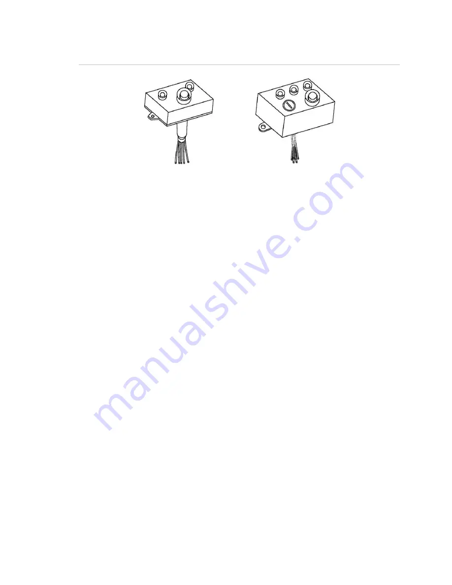
Figure 54: Panic buttons
To install a panic button:
1. Mark the location of the mounting holes, using the panic button as a template.
2. Drill the mounting holes, using a 3/16 in. (5 mm) drill bit.
3. Drill a hole for the panic button wiring, using a 3/4 in. (20 mm) drill bit.
4. Splice a six-conductor 18 AWG cable to the panic button wiring by soldering
the wires and applying heat-shrink tubing to the exposed wire.
Note:
The panic button with key reset has six wires, and the panic button
without key reset has only five. The NC and common wires are both yellow
and are interchangeable.
5. Route the cable to the DVR. See Figure 55 on page 76. Connect the cable to
the connectors as follows:
• Connect the yellow NC and common wires to Digital Input 1 (J3, terminal
1) and 12VDC Out (J3, terminal 9).
• Connect the gray positive wire to 12VDC Out (J3, terminal 9) or any other
available 12 V terminal.
• Connect the green normal wire to Software LED output (J2, terminal 7).
• Connect the red check wire to Camera LED output (J2, terminal 6).
• Connect the white negative wire (present only on the panic button with key
reset) to Ground (J3, terminal 10).
Note:
Digital Input 2 (J3, terminal 2) is typically reserved for the impact
sensor input.
6. Mount the panic button, using the previously drilled holes.
Summary of Contents for PENTA
Page 1: ...PENTA Installation Manual UM TR 1210 ...
Page 5: ...MobileView PENTA Installation Manual iii ...
Page 6: ......
Page 23: ...Chapter 2 Camera installation MobileView PENTA Installation Manual 17 ...
Page 24: ...Chapter 2 Camera installation 18 MobileView PENTA Installation Manual ...
Page 72: ......
Page 92: ...Chapter 6 Testing 86 MobileView PENTA Installation Manual ...
Page 105: ...Appendix A Checklists and worksheets MobileView PENTA Installation Manual 99 ...
Page 106: ......
Page 114: ......


