28
29
ENGLISH
ENGLISH
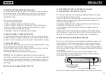
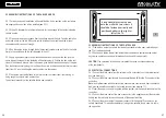
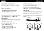
In many cases the connection is on pin 15 of the general terminal board and in any case
it corresponds to an active and positive voltage of +12 VDC generated when the vehicle
ignition key is rotated.
This connection prevents the operation of the satellite dish when the vehicle is moving
or the ignition key is turned for ignition.
DECODER 2
G
R
E
E
N
C
A
B
L
E
G
R
E
E
N
C
A
B
L
E
BLACK CABLE
BLACK CABLE
RED CABLE
RED CABLE
WIRING DIAGRAM, ONE-OUTPUT VERSION
NOTE: THE DECODER AND ITS CABLE ARE NOT INCLUDED
WIRING DIAGRAM, TWO-OUTPUT VERSIONS
NOTE: THE DECODER AND ITS CABLE ARE NOT INCLUDED
TO THE IGNITION KEY OF THE
VEHICLE (+ 12 V CURRENT)
TO THE IGNITION KEY OF THE
VEHICLE (+ 12 V CURRENT)
7
7.1
DECODER
DECODER 1
7.1
11
GB
2
CAUTION! Read all the instructions.
The improper or non observance of these instructions may result in serious damage and
injuries.
KEEP THESE INSTRUCTIONS!
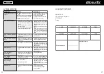
3.1 WORKING AREA
Before switching the system on, always make sure that the working area is free from
obstacles (tree branches, protruding balconies etc.).
RISK OF DAMAGE TO SATELLITE DISH AND VEHICLE!
3.2 SAFETY AND ELECTRIC SUPPLY
The device must be exclusively powered with 12 V, supplied directly from the service bat
tery using cables with a minimum section of 2.5 mm.
If a 12V electric power supply is used instead of the battery, make sure that it is stablised
and able to deliver 3 Amps continuously and 10 Amps for short periods.
Do not use a poor quality battery charger that is not stablised.
3.3 PEOPLE’S SAFETY
Before enabling the opening of the satellite dish, make sure that nobody is on the vehicle
roof. If someone is on the roof of the camper, he/she could be hit bythe satellite dish when
it is opened or closed.
RISK OF SERIOUS INJURY!


