Maintenance
Micro-Ion
®
Module Instruction Manual - 356007-GP
65
In
stallation
O
per
a
tion
Maintenance
Before You
Begin
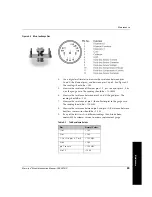
Figure 4-4
Micro-Ion Gauge Pins
4.
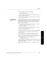
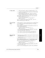
Use a digital multimeter to measure the resistance between pins
2 and 3 (the filament pins), and between pins 1 and 2. See Figure 4-4.
The readings should be < 2
Ω
.
5.
Measure the resistance of filament pins 1, 2, or 3 to any of pins 4, 5, or
6, or the gauge case. The reading should be > 100 M
Ω
.
6.
Measure the resistance between pins 4 and 6 (the grid pins). The
reading should be < 2
Ω
.
7.
Measure the resistance of pin 5 (the collector pin) to the gauge case.
The reading should be > 100 M
Ω
.
8.
Measure the resistance between pin 9 and pin 10. Resistance between
heat-loss sensor wires should be <14
Ω
.
9.
If any of the tests result in different readings than listed above,
contact MKS customer service to order a replacement gauge.
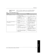
Table 4-2
Test Resistance Values
Pins
Normal Values
1 to 2
< 2
Ω
2 to 3
< 2
Ω
1, 2 or 3 to pins 4, 5, or 6
> 100 M
Ω
4 to 6
< 2
Ω
pin 5 to case
> 100 M
Ω
9 to 10
<14
Ω
Summary of Contents for 356 Micro-Ion Plus Series
Page 2: ......
Page 24: ...24 Micro Ion Module Instruction Manual 356007 GP...
Page 58: ...Chapter 3 58 Micro Ion Module Instruction Manual 356007 GP...
Page 74: ...Index 74 Micro Ion Module Instruction Manual 356007 GP...
Page 75: ......

