Maintenance
Micro-Ion
®
Module Instruction Manual - 356007-GP
61
In
stallation
O
per
a
tion
Maintenance
Before You
Begin
Symptoms, Causes, and
Solutions
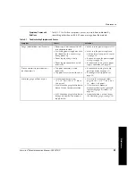
Table 4-1 lists failure symptoms, causes, and solutions indicated by
something other than an RS-485 error message from the module.
Table 4-1
Troubleshooting Symptoms and Causes
Symptom
Causes
Solutions
Gauge indicator does not illuminate.
• Power supply is disconnected, OFF,
or inadequate for load.
• A switching power supply may have
shut down due to a current surge
during power-up.
• Power supply wiring is faulty.
• Power supply connector is wired
incorrectly.
• Make sure the power supply is ON.
• Make sure the power supply can
withstand the startup inrush current
(see page 18).
• Replace or repair the power supply
wiring (see page 18).
• Reconnect the wiring to the power
supply connector (see page 18).
Process control trip point does not
function properly.
• Trip point connector is wired
incorrectly.
• Trip points are set to invalid values.
• Reconnect the wiring to the trip
point connector (see page 21).
• Reconfigure the trip points (see
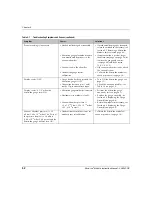
Micro-Ion gauge will not stay on.
• Vacuum chamber pressure
> 2 x 10
–2
Torr (2.66 x 10
–2
mbar,
2.66 pascal).
• Er #6: Micro-Ion gauge failure due to
broken filament or contamination.
• Er #5: Micro-Ion gauge failure due to
damage, contamination, or power
supply failure.
• Decrease the vacuum chamber
pressure to < 2 x 10
–2
Torr (2.66 x
10
–2
mbar, 2.66 pascal).
• If the filament is broken or
mechanical damage has occurred,
replace the gauge assembly (see
page 66).
• If contamination is present, degas
the Micro-Ion gauge (see page 34).
Summary of Contents for 356 Micro-Ion Plus Series
Page 2: ......
Page 24: ...24 Micro Ion Module Instruction Manual 356007 GP...
Page 58: ...Chapter 3 58 Micro Ion Module Instruction Manual 356007 GP...
Page 74: ...Index 74 Micro Ion Module Instruction Manual 356007 GP...
Page 75: ......

