


5
55
5Maintenance and Inspection
Maintenance and Inspection
Maintenance and Inspection
Maintenance and Inspection
Maintenance and inspection procedures
Maintenance and inspection procedures
Maintenance and inspection procedures
Maintenance and inspection procedures
5
55
5-
--
-43
43
43
43
(2)
(2)
(2)
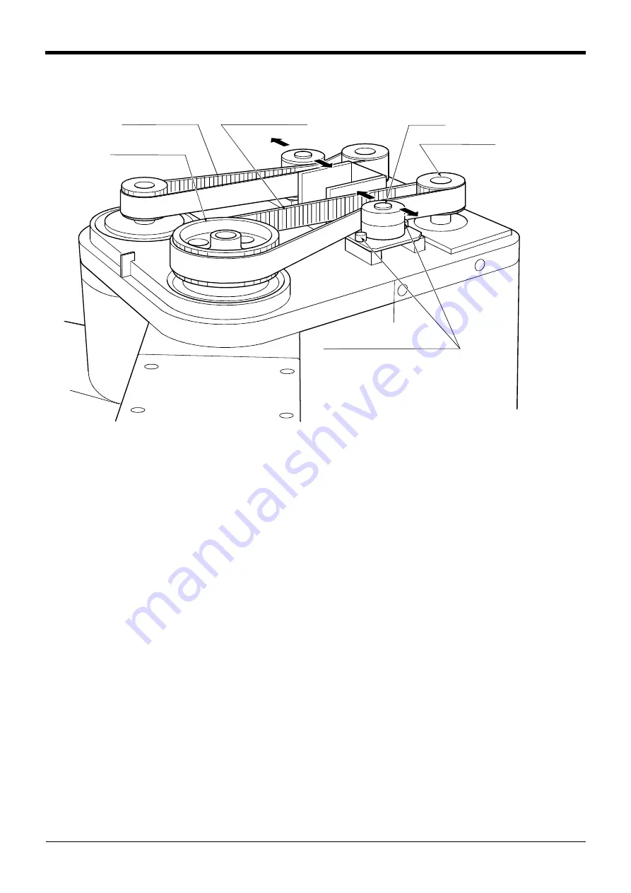
(2) Inspecting, adjusting and replacing the upper base timing belt
Inspecting, adjusting and replacing the upper base timing belt
Inspecting, adjusting and replacing the upper base timing belt
Inspecting, adjusting and replacing the upper base timing belt
Fig.5-5
:
Inspecting, adjusting and replacing the upper base timing belt
Fig.5-5
:
Inspecting, adjusting and replacing the upper base timing belt
Fig.5-5
:
Inspecting, adjusting and replacing the upper base timing belt
Fig.5-5
:
Inspecting, adjusting and replacing the upper base timing belt
■
Inspection method
■
Inspection method
■
Inspection method
■
Inspection method
1
) Confirm that the robot controller power is OFF.
1
) Confirm that the robot controller power is OFF.
1
) Confirm that the robot controller power is OFF.
1
) Confirm that the robot controller power is OFF.
2) Following "Fig. 5-3 Installing/removing the cover" on page 40 remove the shoulder cover.
2) Following "Fig. 5-3 Installing/removing the cover" on page 40 remove the shoulder cover.
2) Following "Fig. 5-3 Installing/removing the cover" on page 40 remove the shoulder cover.
2) Following "Fig. 5-3 Installing/removing the cover" on page 40 remove the shoulder cover.
3) Visually check that the symptoms listed in "(
) Timing belt replacement period" on page 42 above have not
3) Visually check that the symptoms listed in "(
) Timing belt replacement period" on page 42 above have not
3) Visually check that the symptoms listed in "(
) Timing belt replacement period" on page 42 above have not
3) Visually check that the symptoms listed in "(
) Timing belt replacement period" on page 42 above have not
occurred on the belt.
occurred on the belt.
occurred on the belt.
occurred on the belt.
4) Refer to "(5) Timing belt tension" on page 48 for the belt tension, and confirm that the belt deflection is
4) Refer to "(5) Timing belt tension" on page 48 for the belt tension, and confirm that the belt deflection is
4) Refer to "(5) Timing belt tension" on page 48 for the belt tension, and confirm that the belt deflection is
4) Refer to "(5) Timing belt tension" on page 48 for the belt tension, and confirm that the belt deflection is
adequate.
adequate.
adequate.
adequate.
■
Adjustment method
■
Adjustment method
■
Adjustment method
■
Adjustment method
1
) Carry out steps
1
) and 2) in the "
■
Inspection method" above.
1
) Carry out steps
1
) and 2) in the "
■
Inspection method" above.
1
) Carry out steps
1
) and 2) in the "
■
Inspection method" above.
1
) Carry out steps
1
) and 2) in the "
■
Inspection method" above.
2) Loosen the two idler screws
1
. (Do not loosen too far.)
2) Loosen the two idler screws
1
. (Do not loosen too far.)
2) Loosen the two idler screws
1
. (Do not loosen too far.)
2) Loosen the two idler screws
1
. (Do not loosen too far.)
3) While checking the timing belt 2 tension degree, move the idler 5 in the direction of the arrow in the drawing
3) While checking the timing belt 2 tension degree, move the idler 5 in the direction of the arrow in the drawing
3) While checking the timing belt 2 tension degree, move the idler 5 in the direction of the arrow in the drawing
3) While checking the timing belt 2 tension degree, move the idler 5 in the direction of the arrow in the drawing
until it is at the adequate tension position given in "(5) Timing belt tension" on page 48.
until it is at the adequate tension position given in "(5) Timing belt tension" on page 48.
until it is at the adequate tension position given in "(5) Timing belt tension" on page 48.
until it is at the adequate tension position given in "(5) Timing belt tension" on page 48.
4) When moved in the direction of arrow a in the drawing, the belt will be tensed, and when moved in the
4) When moved in the direction of arrow a in the drawing, the belt will be tensed, and when moved in the
4) When moved in the direction of arrow a in the drawing, the belt will be tensed, and when moved in the
4) When moved in the direction of arrow a in the drawing, the belt will be tensed, and when moved in the
direction of arrow b, the belt will be loosened.
direction of arrow b, the belt will be loosened.
direction of arrow b, the belt will be loosened.
direction of arrow b, the belt will be loosened.
5) Do not loosen the belt too much causing it to come off the timing pulleys 3 and 4, or deviate the belt and
5) Do not loosen the belt too much causing it to come off the timing pulleys 3 and 4, or deviate the belt and
5) Do not loosen the belt too much causing it to come off the timing pulleys 3 and 4, or deviate the belt and
5) Do not loosen the belt too much causing it to come off the timing pulleys 3 and 4, or deviate the belt and
pulley teeth engagement when adjusting the tension. Doing so could cause the machine system's origin to
pulley teeth engagement when adjusting the tension. Doing so could cause the machine system's origin to
pulley teeth engagement when adjusting the tension. Doing so could cause the machine system's origin to
pulley teeth engagement when adjusting the tension. Doing so could cause the machine system's origin to
deviate.
deviate.
deviate.
deviate.
6) After adjusting, securely tighten the two idler installation screws
1
. If the idler is improperly tightened, it
6) After adjusting, securely tighten the two idler installation screws
1
. If the idler is improperly tightened, it
6) After adjusting, securely tighten the two idler installation screws
1
. If the idler is improperly tightened, it
6) After adjusting, securely tighten the two idler installation screws
1
. If the idler is improperly tightened, it
could loosen due to vibration.
could loosen due to vibration.
could loosen due to vibration.
could loosen due to vibration.
7) Adjust the other belt with the same method.
7) Adjust the other belt with the same method.
7) Adjust the other belt with the same method.
7) Adjust the other belt with the same method.
■
Replacement method
■
Replacement method
■
Replacement method
■
Replacement method
1
) Carry out steps
1
) and 2) in the "
1
) Carry out steps
1
) and 2) in the "
1
) Carry out steps
1
) and 2) in the "
1
) Carry out steps
1
) and 2) in the "
2) Loosen the two idler installation screws
1
.
2) Loosen the two idler installation screws
1
.
2) Loosen the two idler installation screws
1
.
2) Loosen the two idler installation screws
1
.
3) Remove the old belt, and install a new one.
3) Remove the old belt, and install a new one.
3) Remove the old belt, and install a new one.
3) Remove the old belt, and install a new one.
4) Move the idler 5 in the direction of the arrow in the drawing until it is at the adequate tension position given
4) Move the idler 5 in the direction of the arrow in the drawing until it is at the adequate tension position given
4) Move the idler 5 in the direction of the arrow in the drawing until it is at the adequate tension position given
4) Move the idler 5 in the direction of the arrow in the drawing until it is at the adequate tension position given
in "(5) Timing belt tension" on page 48.
in "(5) Timing belt tension" on page 48.
in "(5) Timing belt tension" on page 48.
in "(5) Timing belt tension" on page 48.
5) After replacing the belt, refer to "5.5 Resetting the origin" on page 55, and reset the origin.
5) After replacing the belt, refer to "5.5 Resetting the origin" on page 55, and reset the origin.
5) After replacing the belt, refer to "5.5 Resetting the origin" on page 55, and reset the origin.
5) After replacing the belt, refer to "5.5 Resetting the origin" on page 55, and reset the origin.
b
a
b
a
3. Timing pulley
2. Timing belt (J4)
5. Idler
4. Timing pulley
1
. Idler installation screw
M3
×
8 (hexagon socket screw)
Timing belt (J3)


